1995 Ford Bronco Starting System Wiring Diagram (20-2) - Starter Relay & TR Sensor

Reference · 1987-1991 BroncoAll 175 wiring diagrams
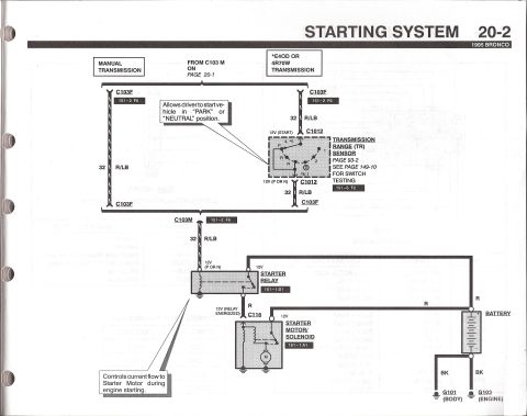
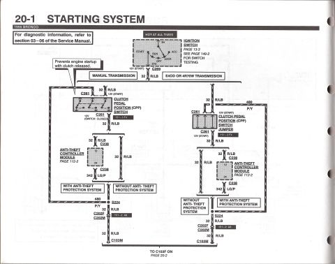
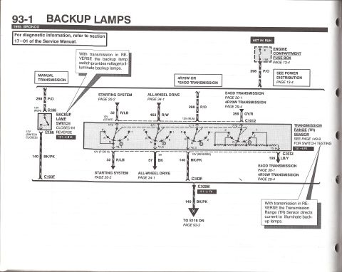
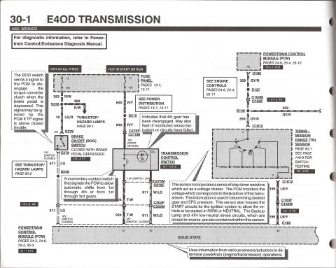












Starting system schematic showing 32 R/LB start circuit through the TR sensor (allows start in Park/Neutral), starter relay, and starter motor solenoid grounds.
Part of 1987-1991 Ford Bronco Wiring Diagrams
This is page 20-2 of the 1995 Ford Bronco electrical/vacuum troubleshooting manual, showing the second half of the Starting System wiring diagram (continued from page 20-1 at connector C103M). It covers both manual transmission and automatic (E4OD or 4R70W) transmission variants. In the automatic branch, circuit 32 R/LB (red/light blue) passes through connector C1012 to the Transmission Range (TR) Sensor, which allows the driver to start the vehicle only in PARK or NEUTRAL; the sensor is detailed on page 93-2 with switch testing on page 149-10 (component location 151-6 F2). On manual transmission vehicles, the circuit passes straight through connectors C103F. Circuit 32 R/LB then feeds the Starter Relay (location 151-1 D1), which controls current flow to the starter motor during engine starting. When energized, the relay sends 12V through wire R and connector C116 to the Starter Motor/Solenoid (location 151-1 A1). The battery feeds the relay via red (R) cables and grounds through black (BK) cables to G101 (body ground) and G103 (engine ground). Grid location references (e.g., 151-2 F6) point to component location views elsewhere in the manual.
This document covers 1995, which may differ from this 1990 Ford Bronco.
Is this accurate? Sign in to help verify it.
Frequently asked questions
- What wire color and circuit number feed the starter relay on a 1995 Bronco?
- Circuit 32, a red/light blue (R/LB) wire, runs from connector C103M to the starter relay, carrying 12V when the transmission is in Park or Neutral.
- What does the Transmission Range (TR) sensor do in the 1995 Bronco starting circuit?
- It allows the driver to start the vehicle only in the PARK or NEUTRAL position, passing 12V (START) through connector C1012 on E4OD or 4R70W automatic transmissions.
- Where can I find TR sensor switch testing in the 1995 Bronco manual?
- The diagram references page 93-2 for the TR sensor and page 149-10 for switch testing; its component location is 151-6 F2.
- What does the starter relay do and where is it located in the manual's component views?
- The starter relay controls current flow to the starter motor during engine starting; its component location reference is 151-1 D1. When energized it sends 12V through connector C116 to the starter motor/solenoid (151-1 A1).
- What are the ground points for the battery in the 1995 Bronco starting system?
- The battery grounds through black (BK) cables to G101 (body ground) and G103 (engine ground).






No comments yet.