1995 Ford Bronco 5.0L Engine Controls Wiring Diagram - PCM & Fuel Pump Relay 24-1

Reference · 1987-1991 BroncoAll 175 wiring diagrams
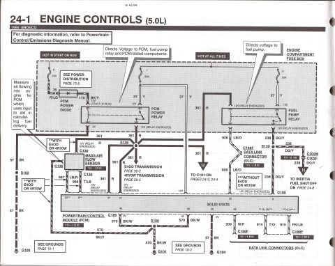
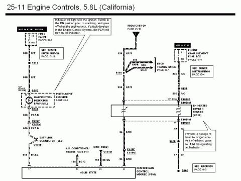
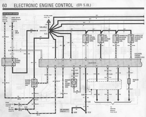
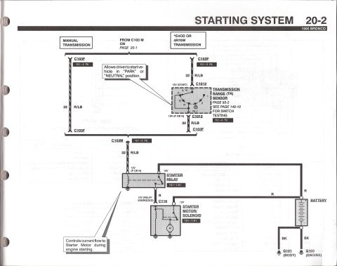
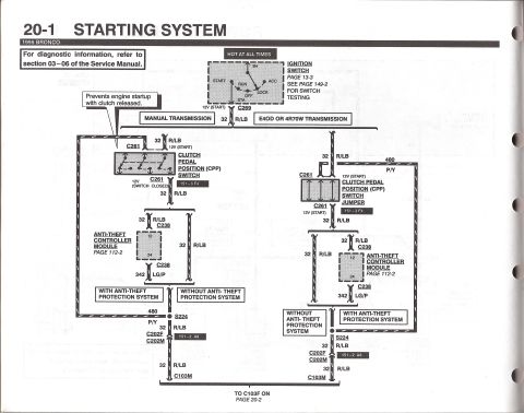












5.0L engine-controls schematic showing PCM, PCM power relay/diode, fuel pump relay, mass air flow sensor, E4OD/4R70W transmission feeds and data link connectors (DLC).
Part of 1987-1991 Ford Bronco Wiring Diagrams
This document is page 24-1 of the 1995 Ford Bronco electrical/vacuum troubleshooting manual, covering Engine Controls for the 5.0L engine, dated 5/12/94. It shows the power distribution portion of the engine control wiring: two 20A fuses in the engine compartment fuse box (one hot in start or run feeding the PCM power diode via circuit 16 R/LG and 175 BK/Y, and hot-at-all-times fuses feeding the PCM power relay and fuel pump relay via circuit 37 Y). The PCM power relay output (circuit 361 R) directs voltage to the PCM, fuel pump relay, mass air flow sensor, and E4OD/4R70W transmission circuits (pages 30-2 and 29-3). The fuel pump relay output feeds circuit 926 LB/O to the data link connector (C198F, without E4OD/4R70W) and circuit 238 DG/Y through connectors C202M/C202F to the inertia fuel shutoff switch (page 24-8). The Powertrain Control Module (PCM) is shown with pin numbers (37, 57, 1, 22, 8, 40, 60, 20, 48, etc.), grounds G100, G101, and G104 via circuits 570 BK/W and 57 BK, and data link connector wiring (209 W/P, 914 T/O, 915 PK/LB to C199F and C198F). Component location grid references such as 151-1 D10 and 151-1 C10 are included.
Is this accurate? Sign in to help verify it.
Frequently asked questions
- What relays power the PCM and fuel pump on a 1995 Bronco 5.0L?
- The PCM power relay and the fuel pump relay, both fed by 20A hot-at-all-times fuses in the engine compartment fuse box via circuit 37 (Yellow). The PCM power relay directs voltage to the PCM, fuel pump relay, and PCM-related components; the fuel pump relay directs voltage to the fuel pump.
- What wire circuit carries power from the PCM power relay?
- Circuit 361, a Red wire, which shows 12V when the relay is energized. It feeds the PCM, mass air flow sensor, fuel pump relay coil, and the E4OD/4R70W transmission circuits.
- What circuit goes to the inertia fuel shutoff switch?
- Circuit 238, Dark Green/Yellow (DG/Y), from the fuel pump relay through splice S139 and connectors C202M/C202F to the inertia fuel shutoff on page 24-8.
- How is the PCM grounded on the 1995 Bronco?
- Through circuit 570 (BK/W and BK/Y) to grounds G100 and G101 via splice S106, and circuit 57 (BK) to ground G104 (see grounds pages 10-1 and 10-2).
- What does the mass air flow sensor do according to this diagram?
- It measures air flowing into the engine for the PCM, which uses the input to aid in calculating fuel delivery. It connects via C130 with circuits 361 R, 967 LB/R, 968 T/LB, and 57 BK.






No comments yet.