SuperMotors SuperMotors SUPERMOTORS Search: try “orange Bronco on 35s”
Home/ Registry/ Ford/ Bronco/ 1987-1991/ “Eddie Bauer”/ Photo supermotors.net/registry/media/904399

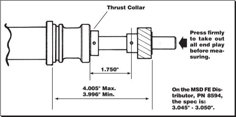
Distributor Gear Installation Diagram - Shaft Dimensions & MSD FE PN 8594 Spec

Dimensioned drawing of a distributor shaft and thrust collar with end-play specifications
Dimensioned drawing of a distributor shaft and thrust collar with end-play specificationsOriginal file
Dimensioned drawing of a distributor shaft and thrust collar with end-play specifications

Reference · 1987-1991 BroncoAll 19 blueprints

Borgeson Steering Intermediate Shaft Measurement Diagram - U-Joint Length B & C Distributor Gear Installation Diagram - Shaft Dimensions & MSD FE PN 8594 Spec Tubing Adapter Blueprint 2.00" OD x 1.375" ID x 3" - 1.125"-12 TPI RH Thread Tubing Adapter Blueprint - 2.00" OD x 1.25" ID Tube, 1.125"-12 RH Thread Insert Tubing Adapter Blueprint 2.00" OD x 1.50" ID Tube, 1.125-12 RH Thread, Mild Steel 1989 Ford Bronco Rear Frame Dimensions Diagram - Rail Width & C-Channel Specs 1989 Ford Bronco Custom Front & Rear Bumper Blueprint - D-Ring & Hitch Layout Hand-Drawn Sheet Metal Bend Layout Sketch - 8ft Panel Profile, 1989 Ford Bronco Ford Bronco Bumper Receiver Hitch Design Sketch - 2" Tube DIY Blueprint Ford Bronco Rock Slider Blueprint - 64" Frame-Mount Slider Dimensions & Weights Ford AOD Transmission Crossmember Fabrication Diagram with Dimensions Hand-Drawn Part Sketch with Dimensions .350 / .200 / .240-.250 - Ford Bronco 19blueprints1987-1991 Ford Bronco More reference 1973-1974 Ford Point-Type Ignition System Circuit Diagram - Coil & DistributorWiring diagram Ford Thermactor Air Bypass Valve Cutaway Diagram - Port IdentificationSchematic Ford Canister Purge Regulator Valve (CANP 9C915) Test Procedure - Figure 11Service procedure Ford 5.8L important engine information decal with 10° BTDC timing check and ASF-32C plugSpec plate Ford 5.0L V8 PCV Valve & Hose Routing Diagram - 9A474, 6B890, 6A664Exploded parts Ford 5.0L/5.8L Air Throttle Body Assembly Diagram - Canister Purge Ports & TPSManual page 1990 Bronco Major Standard Equipment sheet with interior features and functional specs by trimBrochure Ford Thermactor Combination Valve Diagram - Air Bypass/Control Ports LabeledVacuum routing 1990 Ford Bronco Fuse Panel Diagram: Fuse Positions, Amps & Circuits (11-2)Fuse chart Ford V8 Intake Manifold Bolt Tightening Sequence Diagram - Stud LocationsTorque spec

Dimensioned drawing of a distributor shaft and thrust collar with measured tolerances and MSD FE end-play spec of 3.045-3.050 inches.

Part of 1987-1991 Ford Bronco Blueprints

AI caption · Photo 1108 of 1787

This document is a technical line-drawing (blueprint style) showing how to correctly position a distributor drive gear on a distributor shaft, commonly referenced for cam/distributor gear installation. The illustration shows the distributor housing, shaft, thrust collar, and drive gear in cross-section. A callout labels the "Thrust Collar," and an arrow at the shaft end instructs the installer to "Press firmly to take out all end play before measuring." Two dimensional specifications are given: the distance from the thrust collar to the gear reference point is 1.750 inches, and the overall measurement from the housing/collar reference to the far side of the gear must fall between 3.996 inches minimum and 4.005 inches maximum. A note states that on the MSD FE Distributor, part number PN 8594, the specification differs: 3.045" - 3.050". A reader learns the exact gear placement dimensions needed when pressing a distributor gear onto a shaft, the importance of removing shaft end play before taking the measurement, and the alternate spec for the MSD FE distributor. The document itself gives no year, make, model, or engine applicability beyond the MSD FE distributor reference (FE typically indicating Ford FE-series applications).

Is this accurate? Sign in to help verify it.

Frequently asked questions

What is the overall dimension for installing the distributor drive gear?
The overall measurement must be between 3.996" minimum and 4.005" maximum.
What is the distance from the thrust collar to the gear?
The diagram specifies 1.750" between the thrust collar and the gear reference point.
What is the gear installation spec for the MSD FE distributor?
On the MSD FE Distributor, PN 8594, the spec is 3.045" - 3.050".
What must be done before measuring the gear position?
Press firmly on the end of the shaft to take out all end play before measuring.

Comments

No comments yet.

More 1987-1991 Broncos