Ford EEC-IV SD to MAF Computer Pin-Out Chart: Pins 22-48 (1990 Bronco)

Reference · 1987-1991 BroncoAll 175 wiring diagrams
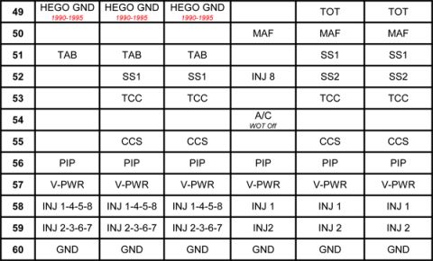
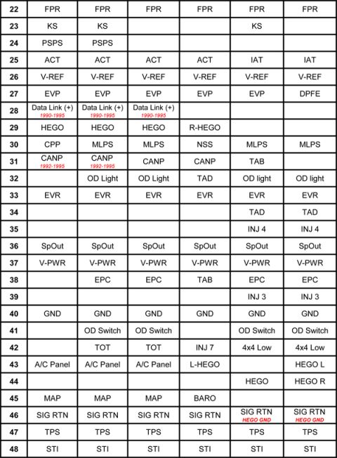
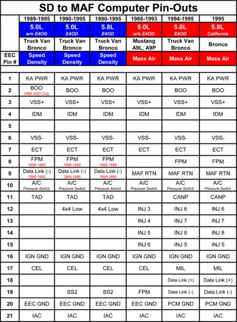
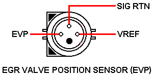
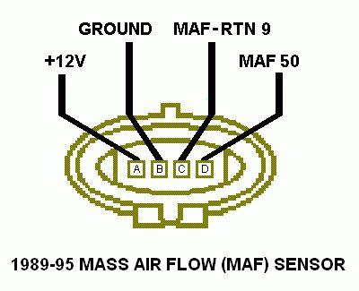
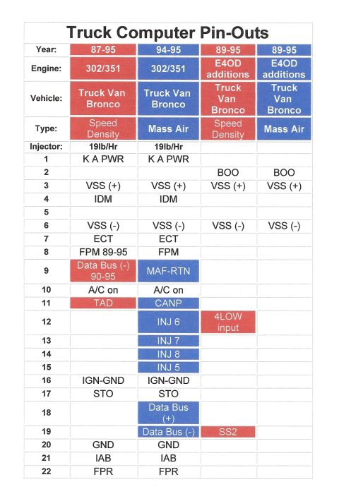



Powertrain control module pin-out chart mapping connector terminals 22 through 48 to signals such as FPR, HEGO, TPS and INJ across engine applications.
Part of 1987-1991 Ford Bronco Wiring Diagrams
This document is one page of a multi-page Ford EEC-IV computer (ECM/PCM) pin-out comparison chart, covering connector pins 22 through 48 across six different computer/calibration configurations (the column headers identifying each configuration appear on another page of the set). For each pin number, the table lists the assigned circuit or signal, such as FPR (pin 22), KS knock sensor (pin 23), PSPS (pin 24), ACT or IAT (pin 25), V-REF (pin 26), EVP or DPFE (pin 27), Data Link (+) noted as 1990-1995 (pin 28), HEGO/R-HEGO (pin 29), CPP/MLPS/NSS (pin 30), CANP with a 1992-1995 note or TAB (pin 31), OD Light/TAD (pin 32), EVR (pin 33), SpOut (pin 36), V-PWR (pin 37), EPC/TAB (pin 38), GND (pin 40), OD Switch (pin 41), TOT/INJ 7/4x4 Low (pin 42), A/C Panel and HEGO L (pin 43), MAP or BARO (pin 45), SIG RTN with HEGO GND notes (pin 46), TPS (pin 47), and STI (pin 48). The chart is useful for comparing speed-density to MAF computer wiring when swapping or diagnosing Ford EEC-IV engine management systems.
Is this accurate? Sign in to help verify it.
Frequently asked questions
- What is on pin 47 of the Ford EEC-IV computer connector?
- Pin 47 is TPS (throttle position sensor) in all six computer configurations shown in the chart.
- Which pin is the Data Link (+) signal on, and what years does it apply to?
- Pin 28 is Data Link (+), noted in the chart as applying to 1990-1995, and it appears in only three of the six configurations.
- What pin carries the CANP (canister purge) signal?
- Pin 31 carries CANP in four configurations (noted as 1992-1995 in two of them); in another configuration pin 31 is TAB instead.
- Where are the ground and signal return pins?
- Pin 40 is GND in all configurations, and pin 46 is SIG RTN in all configurations, with two configurations noting it also serves as HEGO GND.
- Which pin differs between MAP and BARO sensors?
- Pin 45 is MAP in three configurations and BARO in one configuration; it is blank in the remaining two.






No comments yet.