1989-95 Ford MAF Sensor Connector Pinout Diagram - Pins A-D Wiring
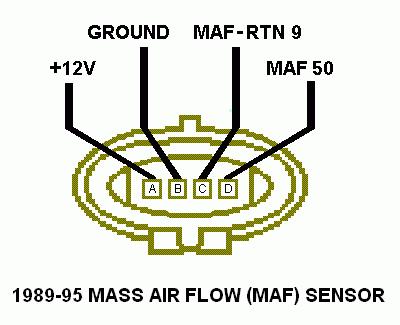
Connector pin-out diagram of a 1989-95 mass air flow (MAF) sensor labeling +12V, ground, MAF-RTN, and MAF terminals.
This document is a pinout diagram for the electrical connector on the 1989-95 Ford Mass Air Flow (MAF) sensor. The drawing shows the oval sensor connector face with four labeled terminals in a row, identified as pins A, B, C, and D. Callout lines link each pin to its circuit function: Pin A carries +12V power, Pin B is GROUND, Pin C is MAF-RTN 9 (the MAF signal return, EEC pin 9), and Pin D is MAF 50 (the MAF signal to EEC pin 50). The caption at the bottom identifies the applicability as the 1989-95 Mass Air Flow (MAF) sensor. A reader can use this diagram to identify which terminal on the MAF sensor connector serves each function when testing the sensor, diagnosing wiring problems, or performing a mass-air conversion. The diagram does not include wire colors, resistance/voltage specifications, or part numbers, only the pin letter positions and their circuit names. It was uploaded to a 1990 Ford Bronco gallery, and the stated 1989-95 range covers that vehicle.
Is this accurate? Sign in to help verify it.
Frequently asked questions
- What is the pinout of the 1989-95 Ford MAF sensor connector?
- Pin A is +12V, Pin B is GROUND, Pin C is MAF-RTN 9 (signal return), and Pin D is MAF 50 (signal).
- Which pin on the MAF sensor connector is power?
- Pin A, labeled +12V, is the power pin.
- Which MAF connector pin is the signal (MAF 50)?
- Pin D is labeled MAF 50.
- What years does this MAF sensor pinout cover?
- The diagram is labeled for the 1989-95 Mass Air Flow (MAF) sensor.
- Where is the MAF signal return on the connector?
- Pin C, labeled MAF-RTN 9, is the MAF signal return.
Comments
More from this build














No comments yet.