Ford EEC-IV SD to MAF Computer Pin-Out Chart: Pins 49-60 (1990-1995)

Reference · 1987-1991 BroncoAll 175 wiring diagrams
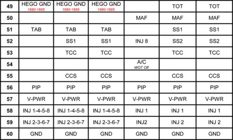
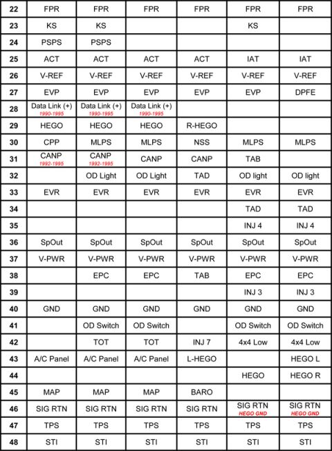
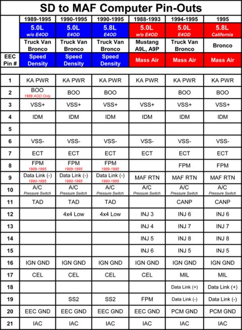
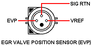
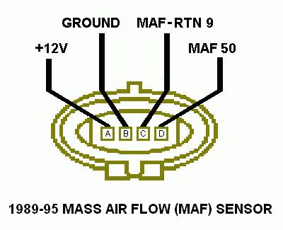












Powertrain control module pin-out chart mapping connector terminals 49 through 60 to signals such as HEGO GND, MAF, PIP, V-PWR and injector circuits.
Part of 1987-1991 Ford Bronco Wiring Diagrams
This document is a page from an EEC (engine computer) pin-out comparison chart, apparently part of a multi-page 'Speed Density (SD) to MAF Computer Pin-Out List' set. It shows computer connector pins 49 through 60 across six columns, each column representing a different computer/calibration variant. Functions listed include HEGO GND (heated exhaust gas oxygen sensor ground, noted as 1990-1995 in three columns), MAF (mass air flow signal), TAB (thermactor air bypass), SS1 and SS2 (shift solenoids), TCC (torque converter clutch), A/C WOT Off, CCS (canister purge/converter clutch-type control), PIP (profile ignition pickup), V-PWR (vehicle power), injector driver outputs (INJ 1-4-5-8 and INJ 2-3-6-7 on bank-fire computers vs. INJ 1, INJ 2, and INJ 8 on others), TOT (transmission oil temperature), and GND (ground) on pin 60. A reader can use this chart to compare which functions occupy pins 49-60 when converting from a speed-density EEC-IV computer to a MAF-based computer, identifying which pins carry the same signal across variants (e.g., PIP on 56, V-PWR on 57, GND on 60) and which differ (e.g., pin 50 MAF only on later columns, pin 49 HEGO GND vs. TOT).
Is this accurate? Sign in to help verify it.
Frequently asked questions
- What is on pin 60 of the Ford EEC computer connector?
- Pin 60 is GND (ground) on all computer variants shown in the chart.
- Which pin carries the MAF signal?
- Pin 50 carries the MAF signal on the mass-air computer columns; it is blank (unused) on the speed-density columns.
- What pins are the fuel injector outputs on?
- On bank-fire computers, pin 58 is INJ 1-4-5-8 and pin 59 is INJ 2-3-6-7. On the other variants, pin 58 is INJ 1, pin 59 is INJ 2, and pin 52 is INJ 8 on one variant.
- Where are PIP and V-PWR located?
- PIP is on pin 56 and V-PWR (vehicle power) is on pin 57 across all six computer variants shown.
- What years does HEGO GND on pin 49 apply to?
- The chart notes HEGO GND on pin 49 applies to 1990-1995 in three of the columns; the last two columns show TOT on pin 49 instead.






No comments yet.