SuperMotors SuperMotors SUPERMOTORS Search: try “orange Bronco on 35s”
Home/ Registry/ Ford/ Bronco/ 1987-1991/ “Eddie Bauer”/ Photo supermotors.net/registry/media/915292

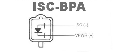
Ford ISC-BPA Idle Air Bypass Solenoid Connector Pinout - ISC (-) & VPWR (+)

ISC-BPA solenoid circuit diagram showing internal diode with ISC and VPWR terminals
ISC-BPA solenoid circuit diagram showing internal diode with ISC and VPWR terminalsOriginal file
ISC-BPA solenoid circuit diagram showing internal diode with ISC and VPWR terminals

Reference · 1987-1991 BroncoAll 175 wiring diagrams

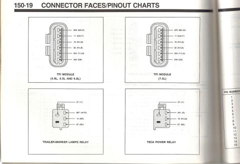
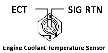
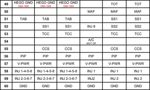
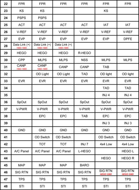
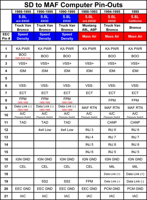
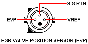
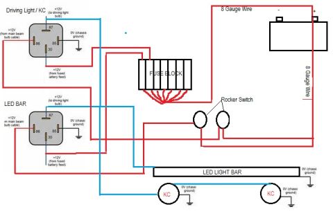
1992-96 Ford Sealed-Bowl TFI Distributor Diagram & Ignition Wiring Schematics Ford TFI Module Connector Pinout - 4.9L 5.0L 5.8L 7.5L Wiring & Relay Diagrams Ford ECT Engine Coolant Temperature Sensor Connector Pinout Diagram Ford ISC-BPA Idle Air Bypass Solenoid Connector Pinout - ISC (-) & VPWR (+) Ford EEC-IV SD to MAF Computer Pin-Out Chart: Pins 49-60 (1990-1995) Ford EEC-IV SD to MAF Computer Pin-Out Chart: Pins 22-48 (1990 Bronco) Ford EEC pins 1-21 speed density to mass air pin-out chart for 5.0L and 5.8L Truck, Van, Bronco and Mustang Ford EGR Valve Position Sensor (EVP) Connector Pinout Diagram - 1990 Bronco Ford 3G Alternator Wiring Diagram - Mega Fuse, Charge Lamp & Wire Colors KC Driving Lights & LED Light Bar Relay Wiring Diagram - Ford Bronco Aux Lights 175wiring diagrams1987-1991 Ford Bronco More reference Ford Thermactor Air Bypass Valve Cutaway Diagram - Port IdentificationSchematic Ford Canister Purge Regulator Valve (CANP 9C915) Test Procedure - Figure 11Service procedure Ford 5.8L important engine information decal with 10° BTDC timing check and ASF-32C plugSpec plate Ford 5.0L V8 PCV Valve & Hose Routing Diagram - 9A474, 6B890, 6A664Exploded parts Ford 5.0L/5.8L Air Throttle Body Assembly Diagram - Canister Purge Ports & TPSManual page 1990 Bronco Major Standard Equipment sheet with interior features and functional specs by trimBrochure Borgeson Steering Intermediate Shaft Measurement Diagram - U-Joint Length B & CBlueprint Ford Thermactor Combination Valve Diagram - Air Bypass/Control Ports LabeledVacuum routing 1990 Ford Bronco Fuse Panel Diagram: Fuse Positions, Amps & Circuits (11-2)Fuse chart Ford V8 Intake Manifold Bolt Tightening Sequence Diagram - Stud LocationsTorque spec

Electrical circuit diagram of the ISC-BPA solenoid showing its internal diode and the ISC negative and VPWR positive terminals.

Part of 1987-1991 Ford Bronco Wiring Diagrams

AI caption · Photo 1262 of 1787

This document is a simple connector pinout diagram labeled "ISC-BPA" (Idle Speed Control - Bypass Air). It shows the face view of a two-pin electrical connector for the ISC-BPA solenoid, with the two terminals identified: one pin labeled "ISC (-)" (the idle speed control signal/ground side) and the other labeled "VPWR (+)" (vehicle power, the positive supply side). A diode symbol is drawn internally between the two terminals, indicating the solenoid contains an internal clamping diode across its coil. The diagram allows a reader to identify which connector cavity carries switched vehicle power and which carries the computer-controlled ISC signal, which is useful for testing the solenoid, back-probing the circuit, or diagnosing idle control problems. The document contains no year, model, engine, wire color, or part number information, it is purely a terminal identification drawing for the ISC-BPA (idle air bypass) solenoid connector. It was uploaded as part of an album of idle air control reference documents attributed to a 1990 Ford Bronco, and nothing in the diagram contradicts that application.

Is this accurate? Sign in to help verify it.

Frequently asked questions

What are the two pins on the ISC-BPA solenoid connector?
The diagram labels one terminal ISC (-) and the other VPWR (+).
Which pin on the ISC-BPA connector is power?
The pin labeled VPWR (+) is the positive power terminal; ISC (-) is the negative/control side.
Does the ISC-BPA solenoid have an internal diode?
Yes, the diagram shows a diode symbol drawn between the two connector terminals, indicating an internal diode across the solenoid.
What does this diagram show?
It shows a face view of the two-pin ISC-BPA solenoid connector with its terminal identifications: ISC (-) and VPWR (+).


Comments

No comments yet.

More 1987-1991 Broncos