Home/
Registry/
Ford/
Crown Victoria/
1998-2011/
“SOLD”/
Photo
supermotors.net/registry/media/928050
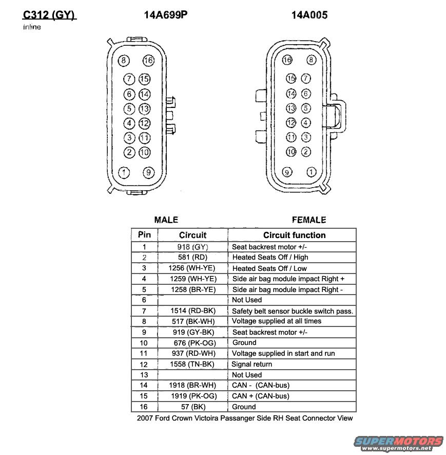
2007 Ford Crown Victoria C312 RH Passenger Seat Connector Pinout Diagram
Reference · 1998-2011 Crown VictoriaAll 29 wiring diagrams
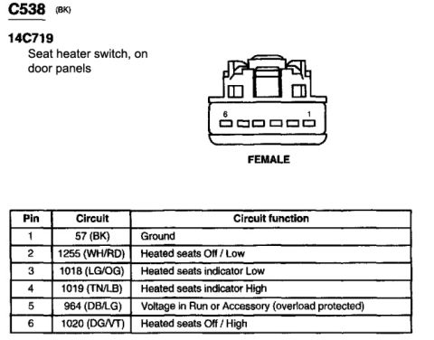
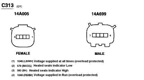

Connector pinout diagram C312 for a 2007 Crown Victoria passenger seat, showing male and female 16-pin views with a circuit color and function chart.
Part of 1998-2011 Ford Crown Victoria Wiring Diagrams
This document is a connector pinout reference for connector C312 (gray, inline), the passenger-side right-hand (RH) seat connector on a 2007 Ford Crown Victoria. It shows face views of both the male (14A699P) and female (14A005) 16-pin connector halves with pin cavity numbering, plus a table listing each pin's circuit number, wire color, and circuit function. Key circuits include: pins 1 and 9 (circuits 918 GY and 919 GY-BK) for the seat backrest motor; pins 2 and 3 (581 RD and 1256 WH-YE) for heated seats Off/High and Off/Low; pins 4 and 5 (1259 WH-YE and 1258 BR-YE) for the right side air bag module impact circuits; pin 7 (1514 RD-BK) for the passenger safety belt buckle switch sensor; pin 8 (517 BK-WH) for constant battery voltage; pin 11 (937 RD-WH) for voltage in start and run; pins 14 and 15 (1918 BR-WH and 1919 PK-OG) for CAN-bus minus and plus; pins 10 and 16 (676 PK-OG and 57 BK) for grounds; pin 12 (1558 TN-BK) for signal return. Pins 6 and 13 are not used. Useful for diagnosing heated seat, seat motor, side airbag, or belt buckle circuits at the seat harness connector.
Is this accurate? Sign in to help verify it.
Frequently asked questions
- What connector is shown in this diagram?
- Connector C312 (GY), an inline gray connector, the passenger side RH seat connector on a 2007 Ford Crown Victoria, showing both the male (14A699P) and female (14A005) halves with 16 pins.
- Which pins carry the heated seat circuits?
- Pin 2, circuit 581 (RD), is Heated Seats Off/High, and pin 3, circuit 1256 (WH-YE), is Heated Seats Off/Low.
- Which pins are for the side air bag module?
- Pin 4, circuit 1259 (WH-YE), is Side air bag module impact Right +, and pin 5, circuit 1258 (BR-YE), is Side air bag module impact Right -.
- Where are power and ground on connector C312?
- Pin 8 (517 BK-WH) is voltage supplied at all times, pin 11 (937 RD-WH) is voltage supplied in start and run, and pins 10 (676 PK-OG) and 16 (57 BK) are grounds.
- Which pins are the CAN-bus wires?
- Pin 14, circuit 1918 (BR-WH), is CAN - and pin 15, circuit 1919 (PK-OG), is CAN + (CAN-bus).

No comments yet.