Home/
Registry/
Ford/
Crown Victoria/
1998-2011/
“SOLD”/
Photo
supermotors.net/registry/media/928052
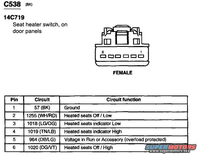
Ford Heated Seat Switch Connector C538 Pinout - Wire Colors & Functions
Reference · 1998-2011 Crown VictoriaAll 29 wiring diagrams
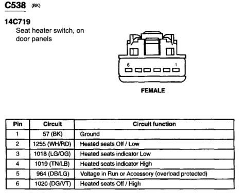
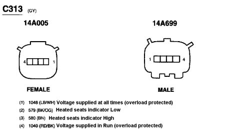
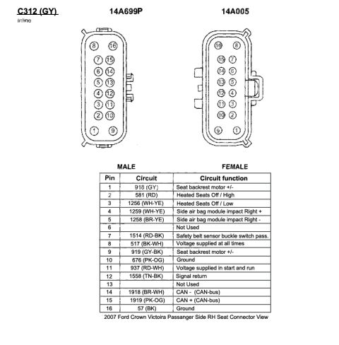
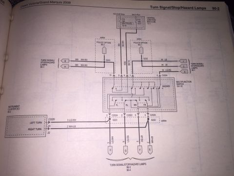
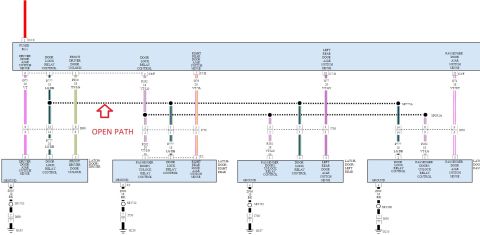
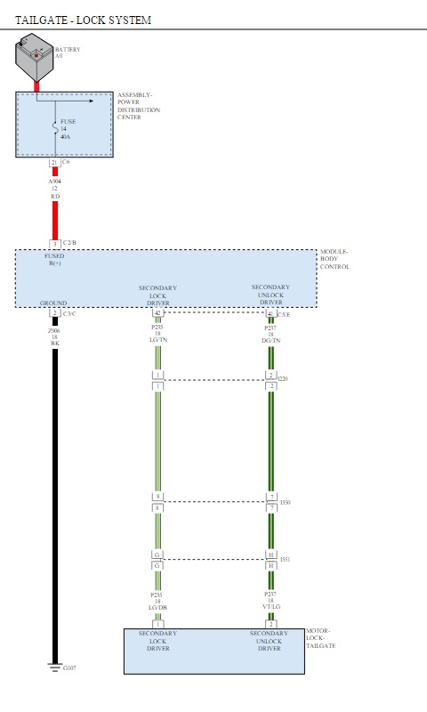
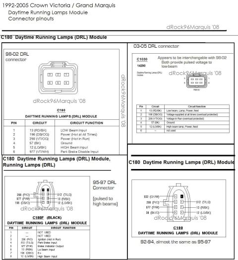
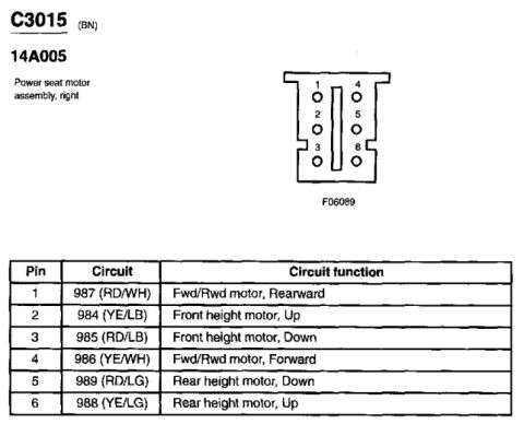

Connector pinout diagram C538 for the seat heater switch, showing a six-pin female view with a circuit color and function chart for heated seat controls.
Part of 1998-2011 Ford Crown Victoria Wiring Diagrams
This document is a connector pinout reference for connector C538 (black), part reference 14C719, the seat heater switch located on the door panels. It includes a face view illustration of the female 6-pin connector with pin numbering (pin 6 to pin 1 across the connector face). A table lists each of the six pins with its circuit number, wire color code, and function: Pin 1 is circuit 57 (black wire) for Ground; Pin 2 is circuit 1255 (white/red) for Heated seats Off/Low; Pin 3 is circuit 1018 (light green/orange) for the Heated seats indicator Low; Pin 4 is circuit 1019 (tan/light blue) for the Heated seats indicator High; Pin 5 is circuit 964 (dark blue/light green) providing voltage in Run or Accessory, overload protected; and Pin 6 is circuit 1020 (dark green/violet) for Heated seats Off/High. A reader can use this diagram to identify wire colors and functions when diagnosing, testing, or retrofitting a heated seat switch circuit. The document itself does not state a specific year, make, or model, but it was uploaded as part of a heated seats documentation set for a 2005 Ford Crown Victoria.
Is this accurate? Sign in to help verify it.
Frequently asked questions
- What is connector C538?
- C538 is a black (BK) 6-pin female connector for the seat heater switch (14C719), located on the door panels.
- Which pin on the heated seat switch connector is ground?
- Pin 1, circuit 57 with a black (BK) wire, is the ground.
- Which pin provides power to the heated seat switch?
- Pin 5, circuit 964 (dark blue/light green, DB/LG), provides voltage in Run or Accessory and is overload protected.
- What wire colors are used for the heated seat indicator lights?
- Pin 3, circuit 1018 (LG/OG) is the indicator Low, and pin 4, circuit 1019 (TN/LB) is the indicator High.
- What circuits control the heated seats Off/Low and Off/High functions?
- Pin 2, circuit 1255 (WH/RD) is Heated seats Off/Low, and pin 6, circuit 1020 (DG/VT) is Heated seats Off/High.

No comments yet.