Home/
Registry/
Ford/
Crown Victoria/
1998-2011/
“SOLD”/
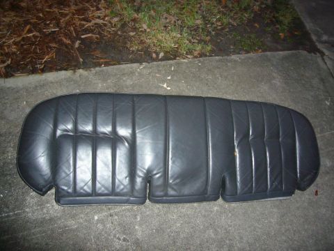
Photo
supermotors.net/registry/media/928051
Ford C313 Heated Seat Connector Pinout - 14A005/14A699 Wire Colors & Circuits

Reference · 1998-2011 Crown VictoriaAll 29 wiring diagrams
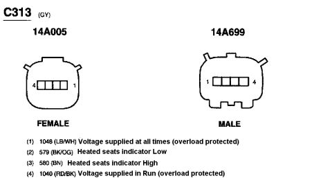

Connector pinout diagram C313 showing female and male four-pin views with heated seat indicator and voltage supply circuit color codes.
Part of 1998-2011 Ford Crown Victoria Wiring Diagrams
This document is a connector pinout diagram for connector C313 (gray, GY), showing both mating halves: the female side labeled 14A005 and the male side labeled 14A699. Each connector is drawn face-on with a 4-pin inline arrangement; the female view is numbered 4 to 1 left-to-right, and the male view is numbered 1 to 4 left-to-right (mirror images, as expected for mating faces). Below the drawings is a legend listing all four circuits by pin: Pin 1 is circuit 1048 (light blue/white), voltage supplied at all times (overload protected); Pin 2 is circuit 579 (black/orange), heated seats indicator Low; Pin 3 is circuit 580 (brown), heated seats indicator High; and Pin 4 is circuit 1040 (red/black), voltage supplied in Run (overload protected). A reader can use this page to identify wire colors and functions when diagnosing or repairing the heated seat circuit at connector C313, verifying power feeds (constant and Run-only) and the low/high heated seat indicator signal wires. It was uploaded in association with a 2005 Ford Crown Victoria heated seat wiring set, though the page itself carries no year, make, or model markings.
Is this accurate? Sign in to help verify it.
Frequently asked questions
- What are the pin functions of connector C313?
- Pin 1: circuit 1048 (LB/WH), voltage supplied at all times (overload protected); Pin 2: circuit 579 (BK/OG), heated seats indicator Low; Pin 3: circuit 580 (BN), heated seats indicator High; Pin 4: circuit 1040 (RD/BK), voltage supplied in Run (overload protected).
- What color is the C313 connector?
- The document identifies C313 as GY (gray).
- Which wire at C313 has constant power?
- Pin 1, circuit 1048 (light blue/white), is voltage supplied at all times and is overload protected.
- Which wire is powered only in Run?
- Pin 4, circuit 1040 (red/black), is voltage supplied in Run (overload protected).
- What are the connector body part identifiers shown?
- The female connector is labeled 14A005 and the male connector is labeled 14A699.


No comments yet.