Ford Bronco & F-Series 4.9L Oil Pressure Gauge & Sender Diagram (33-32-3)

Reference · 1987-1991 BroncoAll 61 exploded parts diagrams
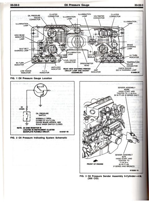








Oil pressure gauge service page: cluster bulb/connector location, oil-pressure indicating schematic (switch closes 4.5-7.5 psi, 20 ohm resistor) and 4.9L 300 sender torque 8-18 ft-lb.
Part of 1987-1991 Ford Bronco Exploded Parts Diagrams
This is page 33-32-3 of a Ford shop manual section covering the Oil Pressure Gauge for E-Series, F-Series (F-150 through F-350, F-Super Duty) and Bronco trucks. Figure 1 shows a rear view of the instrument cluster (printed circuit lamp and socket assemblies) identifying the oil pressure gauge connector, cluster connectors, illumination lamps, high beam indicator, seat belt warning lamp, brake warning lamp, LH/RH turn indicators, fuel gauge connector, speedometer head, temperature gauge connector, anti-lock indicator, 4x4 and low range indicators, amp indicator, and the CHECK ENGINE (EEC-IV) warning lamp. Figure 2 is the oil pressure indicating system schematic: a normally open oil pressure switch that closes at 4.5-7.5 PSI, with a 20-ohm resistor located in the instrument cluster backplate flexible circuit, causing the gauge to read approximately mid-scale when the switch closes. Figure 3 shows the oil pressure sender assembly locations on the 6-cylinder 4.9L (300 CID) engine: sender 9D290 for E-Series and sender 9278 for F-Series and Bronco, both hand-started and tightened to 11-24 N·m (8-18 ft-lb). Partially legible text covers gauge removal/installation procedures (referring to Section 33-51) and sending unit replacement with the same torque specification.
Is this accurate? Sign in to help verify it.
Frequently asked questions
- At what pressure does the Ford oil pressure switch close?
- The oil pressure switch is normally open and closes at 4.5-7.5 PSI. When it closes, the gauge reads approximately mid-scale.
- Where is the 20-ohm resistor for the oil pressure gauge located?
- Per the note in Fig. 2, the 20 ohm resistor is located in the instrument cluster backplate flexible circuit.
- What is the torque spec for the oil pressure sender on the 4.9L (300 CID) 6-cylinder?
- Hand start the sender and tighten to 11-24 N·m (8-18 ft-lb). This applies to both sender 9D290 (E-Series only) and sender 9278 (F-Series and Bronco).
- Which oil pressure sender is used on the Bronco and F-Series 300 six?
- Sender assembly 9278 is used on F-Series and Bronco; sender assembly 9D290 is used on E-Series.
- What connectors and lamps are on the back of the instrument cluster?
- Fig. 1 shows the oil pressure gauge, fuel gauge, temperature gauge, voltmeter and cluster connectors, plus illumination lamps, high beam, seat belt, brake warning, LH/RH turn, anti-lock, 4x4, low range, amp indicators, speedometer head, and the CHECK ENGINE (EEC-IV) warning lamp.






No comments yet.