Ford Bronco EVP Sensor & EGR Valve Location Diagram - EFI V8 Engine

Reference · 1987-1991 BroncoAll 111 schematics
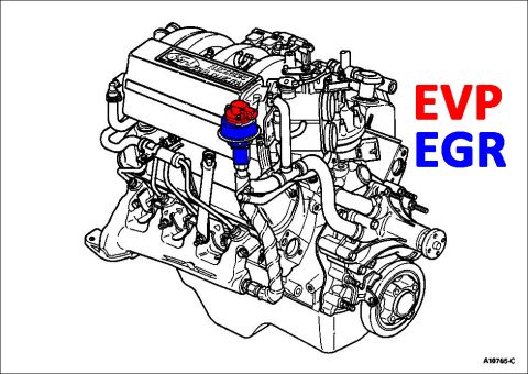
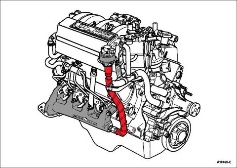
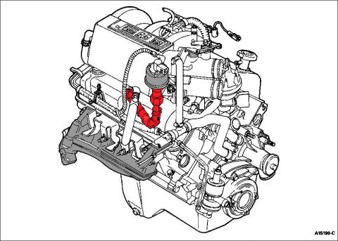












Engine component location diagram highlighting the EVP/EGR valve position on the V8 engine.
Part of 1987-1991 Ford Bronco Schematics
This document is a component-location schematic showing a Ford fuel-injected V8 engine in a detailed line-art illustration. Two components are highlighted in color and labeled in large text at the right side of the image: the EGR valve (highlighted in blue) and the EVP sensor (highlighted in red), which sits directly on top of the EGR valve. The parts are mounted on the upper intake manifold area near the throttle body, on the driver's side/front region of the engine. The engine's upper intake plenum carries a Ford badge plaque referencing fuel injection. The Ford illustration reference number A10765-C appears in the lower-right corner. A reader can use this diagram to visually locate the EGR (Exhaust Gas Recirculation) valve and its EVP (EGR Valve Position) sensor on the engine for inspection, diagnosis, or replacement. No fuse data, wire colors, torque specs, part numbers (other than the figure number), or year/model applicability statements are printed on the document itself; it is purely a pictorial location reference. The file was uploaded to a 1990 Ford Bronco gallery and is consistent with a Ford EFI V8 engine layout.
Is this accurate? Sign in to help verify it.
Frequently asked questions
- Where is the EVP sensor located on this Ford engine?
- Per the diagram, the EVP sensor (highlighted in red) is mounted directly on top of the EGR valve on the upper intake manifold area of the engine.
- Where is the EGR valve on this engine?
- The EGR valve (highlighted in blue) is shown mounted on the upper intake manifold area, near the throttle body at the front/upper portion of the engine, with the EVP sensor on top of it.
- What components does this diagram identify?
- It identifies two components: the EVP (labeled in red) and the EGR (labeled in blue), shown highlighted on a Ford fuel-injected engine illustration.
- Is there a figure or illustration number on this diagram?
- Yes, the illustration reference number A10765-C appears in the lower-right corner.






No comments yet.