Ford E4OD Cooler Line Fittings Diagram - Inlet Check Valve & Outlet (TB-3928-A)

Reference · 1987-1991 BroncoAll 111 schematics

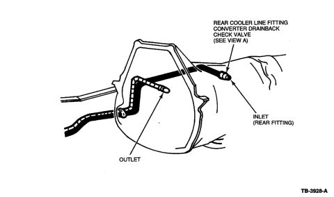












Diagram of the transmission case identifying the rear cooler-line fitting drainback check valve, inlet and outlet locations.
Part of 1987-1991 Ford Bronco Schematics
This document is a line-art schematic illustration showing the transmission cooler line fittings on the side of an automatic transmission case (uploaded as part of an E4OD return fitting check ball reference set). The drawing depicts the transmission and bellhousing area with two cooler line fittings identified by callout arrows. The rear fitting is labeled 'REAR COOLER LINE FITTING / CONVERTER DRAINBACK CHECK VALVE (SEE VIEW A)' and is also identified with a second arrow as the 'INLET (REAR FITTING).' The front fitting is labeled 'OUTLET.' The illustration reference number 'TB-3928-A' appears at the lower right, suggesting it comes from a Ford technical bulletin or service publication. From this diagram, a reader can learn which of the two cooler line ports on the transmission is the inlet (the rear fitting, which contains the converter drainback check valve) and which is the outlet (the front fitting), important information when routing or replacing transmission cooler lines or installing an auxiliary cooler, since the check valve must be in the rear (inlet) position. A referenced 'View A' detail of the check valve is not shown on this page and presumably appears on a companion page in the set.
Is this accurate? Sign in to help verify it.
Frequently asked questions
- Which E4OD cooler line fitting contains the converter drainback check valve?
- The rear cooler line fitting contains the converter drainback check valve, per the callout 'REAR COOLER LINE FITTING CONVERTER DRAINBACK CHECK VALVE (SEE VIEW A).'
- Which cooler line fitting on the transmission is the inlet?
- The rear fitting is the inlet, the diagram labels it 'INLET (REAR FITTING).'
- Where is the cooler line outlet located on the transmission?
- The outlet is the forward fitting on the transmission case, identified in the diagram by the 'OUTLET' callout.
- Where can I see detail of the drainback check valve itself?
- The diagram refers you to 'VIEW A' for the check valve detail; that view is not on this page and appears to be on a companion page in the set.






No comments yet.