Ford 5.8L EFI Engine EGR Tube Routing Diagram - 1990 Bronco (A10765-C)

Reference · 1987-1991 BroncoAll 110 schematics
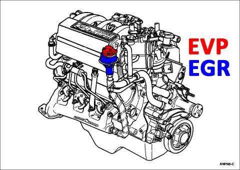
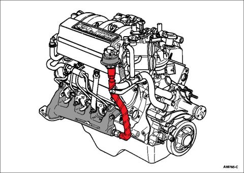
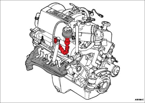
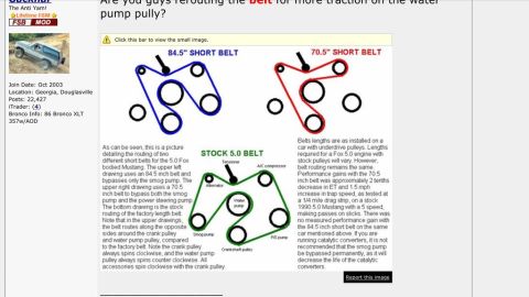
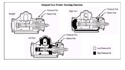


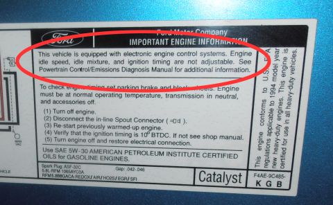
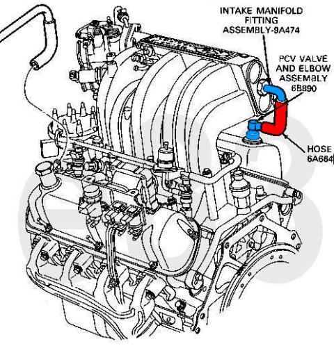


Engine schematic line drawing with a hose highlighted in red to show its routing path across the engine, ref A16765-C.
Part of 1987-1991 Ford Bronco Schematics
This document is a single line-art schematic illustration (figure number A10765-C) of a Ford V8 engine equipped with electronic fuel injection, shown in a three-quarter front perspective view. The uploader identifies it as showing the 5.8L EFI engine's EGR (exhaust gas recirculation) tube routing on a 1990 Ford Bronco. The illustration highlights, in red, the EGR tube path: it begins near the EGR valve at the upper intake/throttle body area, curves downward along the passenger-side front of the engine, and connects into the exhaust manifold region. The exhaust manifold itself is shaded gray for reference. The valve cover in the drawing carries a Ford oval badge with 'Electronic Fuel Injection' lettering. There are no callouts, part numbers (other than the figure code), torque specifications, or legends on the drawing. A reader can learn the physical location and routing of the EGR tube relative to the EGR valve, intake manifold, valve cover, exhaust manifold, water pump, and crankshaft pulley, which is useful when diagnosing EGR system faults or replacing the EGR tube. The figure is part of a larger album of 1990 Bronco emissions and Thermactor system diagrams.
Is this accurate? Sign in to help verify it.
Frequently asked questions
- What does this diagram show?
- It is a line drawing of a Ford V8 electronic fuel injection engine with the EGR tube routing highlighted in red, running from the EGR valve area at the upper intake down to the exhaust manifold.
- Where does the EGR tube connect on this engine?
- Per the highlighted routing, the tube runs from the EGR valve near the upper intake/throttle body area, down the front side of the engine, and into the exhaust manifold region.
- Is there a figure or reference number on this diagram?
- Yes, the figure is marked A10765-C in the lower right corner.
- Does the diagram list part numbers or torque specs?
- No. Aside from the figure code A10765-C and the 'Electronic Fuel Injection' badge on the valve cover, no part numbers, torque values, or callout labels are shown.






No comments yet.