5-Pin Automotive Relay Wiring Diagram - Pinout 30 85 86 87 87a Explained
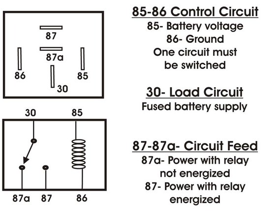
Reference diagram of a standard 5-pin automotive relay explaining terminals 30 load, 85/86 control coil, 87 energized feed and 87a de-energized feed.
This document is a reference schematic explaining the pinout and function of a standard 5-pin automotive relay (Bosch/ISO style). The upper illustration shows the physical terminal layout on the bottom of the relay, with terminals labeled 87, 87a, 86, 30, and 85. The lower illustration shows the internal circuitry: a switch contact connecting terminal 30 to either 87a or 87, and an electromagnetic coil between terminals 85 and 86. Text callouts explain each circuit: terminals 85 and 86 form the Control Circuit, where 85 receives battery voltage and 86 goes to ground, with the note that one of these circuits must be switched. Terminal 30 is the Load Circuit, described as the fused battery supply. Terminals 87 and 87a form the Circuit Feed: 87a provides power when the relay is not energized (normally closed), while 87 provides power when the relay is energized (normally open). A reader can learn how to identify relay terminals, how the internal switching works, and how to wire a relay for controlling loads. The document is generic and not tied to a specific vehicle year, make, or model.
Is this accurate? Sign in to help verify it.
Frequently asked questions
- What do terminals 85 and 86 do on an automotive relay?
- Terminals 85 and 86 form the control circuit: 85 receives battery voltage and 86 goes to ground. One of these circuits must be switched.
- What is terminal 30 on a relay?
- Terminal 30 is the load circuit, which is the fused battery supply.
- What is the difference between relay terminals 87 and 87a?
- 87a provides power when the relay is not energized, while 87 provides power when the relay is energized.
- How is a 5-pin relay laid out physically?
- The diagram shows terminal 87 at top, 87a below it, 30 at the bottom center, with 86 on the left and 85 on the right.
Comments
More from this build














No comments yet.