Ford 5.8L Secondary Air System Diagram - AIRB/AIRD Valve & Air Pump Locations

Reference · 1987-1991 BroncoAll 111 schematics
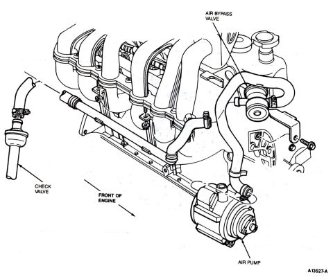
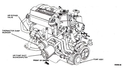
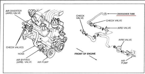
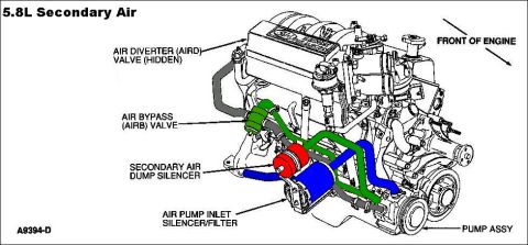









5.8L secondary air schematic showing the air diverter and bypass valves, dump silencer, inlet filter and air pump routing on the engine.
Part of 1987-1991 Ford Bronco Schematics
This document is a labeled schematic drawing of the secondary air (Thermactor) system on a Ford 5.8L engine, uploaded to a 1990 Ford Bronco gallery. The illustration shows a perspective view of the engine with an arrow indicating the front of the engine. Color-coded hoses and components highlight the routing of the secondary air system. Callouts identify five components: the Air Diverter (AIRD) Valve, which is noted as hidden from view; the Air Bypass (AIRB) Valve (highlighted in green area); the Secondary Air Dump Silencer (highlighted in red); the Air Pump Inlet Silencer/Filter (highlighted in blue); and the Pump Assembly located at the lower front of the engine. The figure reference number A9394-D appears in the lower left corner. A reader can use this diagram to locate secondary air injection components on the 5.8L engine, understand how the air pump connects through the bypass and diverter valves, and identify the silencer/filter locations for diagnosis or hose routing during repair of the emissions air injection system.
Is this accurate? Sign in to help verify it.
Frequently asked questions
- What components are shown in the 5.8L secondary air system diagram?
- The diagram labels the Air Diverter (AIRD) Valve (hidden), the Air Bypass (AIRB) Valve, the Secondary Air Dump Silencer, the Air Pump Inlet Silencer/Filter, and the Pump Assembly.
- Where is the air pump assembly located on the 5.8L engine?
- According to the diagram, the pump assembly is at the lower front area of the engine, with the front of the engine indicated by an arrow to the right of the illustration.
- Is the AIRD valve visible on the engine?
- The diagram notes that the Air Diverter (AIRD) Valve is hidden; its callout points toward the rear/top area of the engine.
- What is the figure reference number for this diagram?
- The diagram is marked A9394-D in the lower left corner.






No comments yet.