1990 Ford Bronco 5.0L Thermactor Air Pump, Bypass Valve & Silencer Diagram
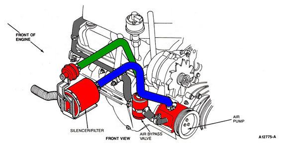
Secondary air schematic (front view) with color-coded hoses connecting the silencer/filter, air bypass valve and air pump.
This document is a line-art schematic (illustration number A12775-A) showing the front view of an engine's secondary air injection (Thermactor) system components. An arrow at the upper left indicates the direction of the front of the engine. Three components are called out and highlighted in red: the silencer/filter (a cylindrical canister mounted at the front-left of the engine with a corrugated intake snorkel), the air bypass valve (a small cylindrical valve mounted low on the engine front), and the belt-driven air pump (shown with its pulley at the lower right). Colored hose routing has been added by the uploader: a green hose runs from the silencer/filter area up and over the engine, and a blue hose runs from near the silencer/filter down to the air pump inlet, with additional gray hoses shown connecting the air bypass valve and other fittings. The drawing also depicts surrounding engine hardware such as the valve cover, fuel pump area, alternator, and drive pulleys for spatial reference. A reader can learn where the silencer/filter, air bypass valve, and air pump are physically located on the front of the engine and how the associated air hoses are routed between them.
Is this accurate? Sign in to help verify it.
Frequently asked questions
- Where is the air pump located on this engine?
- Per the diagram, the belt-driven air pump with its pulley is mounted low on the front of the engine, on the right side of the front view, below the alternator.
- What components are identified in this schematic?
- The diagram labels three components: the silencer/filter, the air bypass valve, and the air pump, all shown from the front view of the engine.
- Where does the air bypass valve sit relative to the air pump?
- The air bypass valve is shown mounted just to the left of (inboard of) the air pump, low on the front of the engine, connected to the pump by short hoses.
- What is the illustration reference number for this diagram?
- The drawing is identified as A12775-A in the lower right corner.
- How is the silencer/filter connected in the system?
- The silencer/filter is the cylindrical canister at the front-left with a corrugated snorkel; highlighted hoses (blue and green in this colorized copy) route from the silencer/filter area toward the air pump and over the top of the engine.
Comments
More from this build














No comments yet.