1990 Ford Bronco 5.8L Thermactor Air Pump & Bypass Valve Diagram (A9394-B)
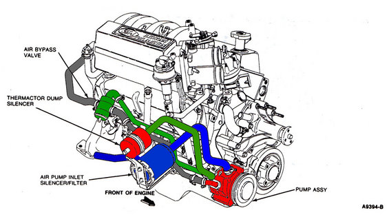
Secondary air schematic with color-coded routing of the air bypass valve, thermactor dump silencer, inlet filter and air pump.
This document is a labeled line-art schematic of the Thermactor (secondary air injection) system components on a Ford EFI V8 engine, shown from the front-left perspective with an arrow indicating 'FRONT OF ENGINE.' The intake plenum is embossed 'Ford Electronic Fuel Injection.' Four components are called out with leader lines and highlighted in color for clarity: the AIR BYPASS VALVE (green, mounted near the front of the engine with attached hoses), the THERMACTOR DUMP SILENCER (red, a small canister ahead of the engine), the AIR PUMP INLET SILENCER/FILTER (blue, a larger cylindrical canister mounted low at the front), and the PUMP ASSY (red, the belt-driven air pump with pulley at the lower right/front of the engine). Colored hose routings (green, blue, gray) show how air flows between the pump, silencers, and bypass valve. The figure carries Ford illustration reference number A9394-B. A reader can learn the physical location and hose routing of the emissions air pump system components, which is useful for identifying, diagnosing, or replacing Thermactor/secondary air parts. The drawing itself contains no year, model, or engine displacement text; it was uploaded as applying to a 1990 Ford Bronco 5.8L.
Is this accurate? Sign in to help verify it.
Frequently asked questions
- What Thermactor components are identified in this diagram?
- The diagram labels four components: the Air Bypass Valve, the Thermactor Dump Silencer, the Air Pump Inlet Silencer/Filter, and the Pump Assembly (air pump).
- Where is the air pump (Pump Assy) located on the engine?
- The Pump Assy is shown mounted low at the front of the engine (highlighted in red), a belt-driven unit with a pulley, positioned toward the passenger side of the front of the engine in the drawing.
- Where is the air pump inlet silencer/filter located?
- It is shown as a large cylindrical canister (highlighted in blue) mounted low at the front of the engine, connected by hose to the air pump.
- What is the Ford illustration reference number for this diagram?
- The drawing is marked A9394-B in the lower right corner.
- How is the engine orientation indicated in the drawing?
- A label 'FRONT OF ENGINE' with an arrow at the bottom of the diagram points toward the front of the engine.
Comments
More from this build














No comments yet.