Home/
Registry/
Ford/
Bronco/
1987-1991/
“Eddie Bauer”/
Photo
supermotors.net/registry/media/1047966
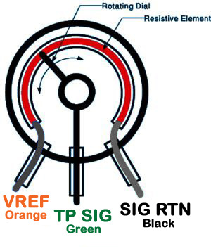
Ford TPS Throttle Position Sensor Wiring Diagram - VREF, TP SIG, SIG RTN Colors
Reference · 1987-1991 BroncoAll 111 schematics
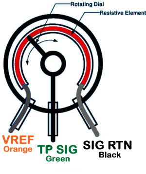














Schematic of a throttle position sensor potentiometer showing the rotating wiper, resistive element and VREF/TP SIG/SIG RTN leads.
Part of 1987-1991 Ford Bronco Schematics
This document is a color schematic diagram of a Throttle Position Sensor (TPS), showing its internal construction and wiring connections. The illustration depicts the sensor as a circular component with two labeled internal parts: the "Rotating Dial" (the wiper arm that sweeps across the sensor as the throttle moves, shown with directional arrows indicating rotation) and the "Resistive Element" (shown in red as an arc-shaped track inside the sensor housing). Three terminal wires emerge from the bottom of the sensor, each labeled with its function and wire color: VREF (reference voltage) on an Orange wire, TP SIG (throttle position signal) on a Green wire, and SIG RTN (signal return/ground) on a Black wire. A reader can learn from this diagram how a potentiometer-style throttle position sensor works, the rotating wiper contacts the resistive element and outputs a variable voltage on the signal wire proportional to throttle angle, and which wire color corresponds to which circuit, useful for testing or troubleshooting the sensor with a multimeter. The document was uploaded to a 1990 Ford Bronco gallery, though the diagram itself contains no year, make, or model markings.
Is this accurate? Sign in to help verify it.
Frequently asked questions
- What are the three wires on the throttle position sensor and their colors?
- VREF (Orange), TP SIG (Green), and SIG RTN (Black).
- What color is the TPS signal wire?
- The TP SIG (throttle position signal) wire is Green.
- What color is the TPS reference voltage wire?
- The VREF wire is Orange.
- What are the internal parts of the TPS shown in the diagram?
- The diagram labels a Rotating Dial and a Resistive Element inside the sensor.
- Which wire is the signal return (ground) on the TPS?
- SIG RTN is the Black wire.






No comments yet.