Home/
Registry/
Ford/
Bronco/
1992-1996/
“Eddie Bauer”/
Photo
supermotors.net/registry/media/1001893
Fiveology Racing TPS Calibration Kit Instructions - Ford 5.0 TPS Adjustment

Reference · 1992-1996 BroncoAll 142 service procedures
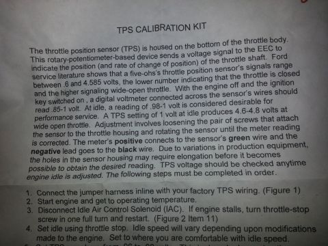
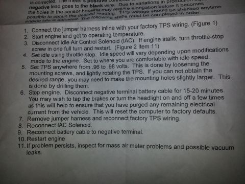
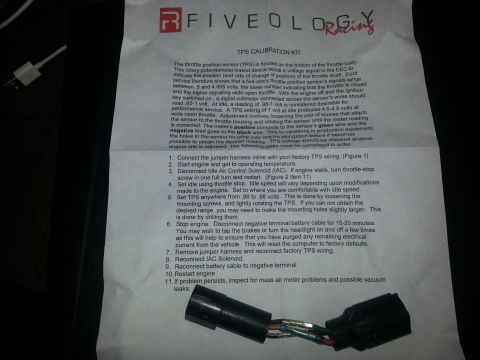
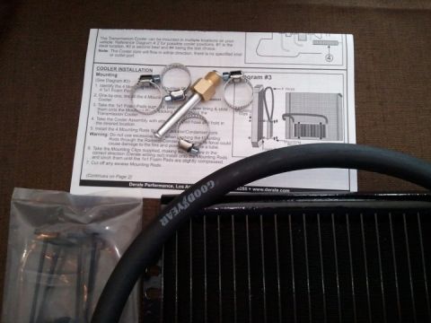
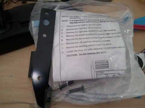




Fiveology Racing TPS calibration kit instruction sheet: throttle position sensor signals .6-4.585V, set idle to .96-.98 volts by rotating the sensor; green wire positive, black ground.
Part of 1992-1996 Ford Bronco Service Procedures
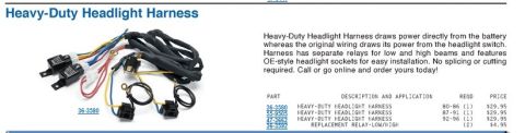
This document is the instruction sheet for the Fiveology Racing TPS Calibration Kit, a jumper harness used to check and adjust the throttle position sensor (TPS) on Ford EEC-equipped engines (the text references Ford 'five-oh' / 5.0L service literature). It explains that the TPS is a rotary potentiometer mounted on the bottom of the throttle body, with a signal range of .6 to 4.585 volts (closed throttle to wide-open throttle). With key on/engine off, the sensor should read .85-1 volt; a reading of .98-1 volt at idle is desirable for performance use, and 1 volt at idle yields 4.6-4.8 volts at WOT. Voltmeter hookup is specified: positive lead to the sensor's green wire, negative lead to the black wire. An 11-step procedure follows: connect the jumper harness inline with factory TPS wiring, warm the engine, disconnect the IAC solenoid, set idle with the throttle stop, adjust TPS to .96-.98 volts (drilling/elongating mounting holes if needed), disconnect the battery negative terminal for 15-20 minutes to reset the computer, then reconnect everything and restart. It also advises checking for mass air meter problems and vacuum leaks if issues persist. A photo shows the supplied inline jumper harness with connectors.
Is this accurate? Sign in to help verify it.
Frequently asked questions
- What voltage should the TPS be set to at idle?
- The instructions say to set the TPS anywhere from.96 to.98 volts; a reading of.98-1 volt at idle is considered desirable for performance service.
- How do you connect the voltmeter to the TPS?
- The meter's positive lead connects to the sensor's green wire and the negative lead goes to the black wire, with the engine off and ignition key switched on.
- What is the normal TPS signal voltage range?
- Ford service literature shows the throttle position sensor's signals range between.6 and 4.585 volts, the lower number indicating closed throttle and the higher signaling wide-open throttle. A 1 volt idle setting produces 4.6-4.8 volts at wide open throttle.
- How do you reset the computer after adjusting the TPS?
- Stop the engine and disconnect the negative battery cable for 15-20 minutes; tapping the brakes or turning the headlights on and off helps purge remaining electrical current. This resets the computer to factory defaults.
- What if I can't get the TPS into the desired voltage range?
- Loosen the mounting screws and lightly rotate the TPS; if the range still can't be reached, the mounting holes may need to be made slightly larger by drilling them.






No comments yet.