Home/
Registry/
Ford/
Bronco/
1992-1996/
“Eddie Bauer”/
Photo
supermotors.net/registry/media/1001895
Ford 5.0 TPS Calibration Kit Instructions - Throttle Position Sensor Adjustment
Reference · 1992-1996 BroncoAll 142 service procedures
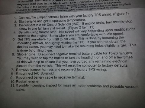
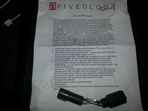



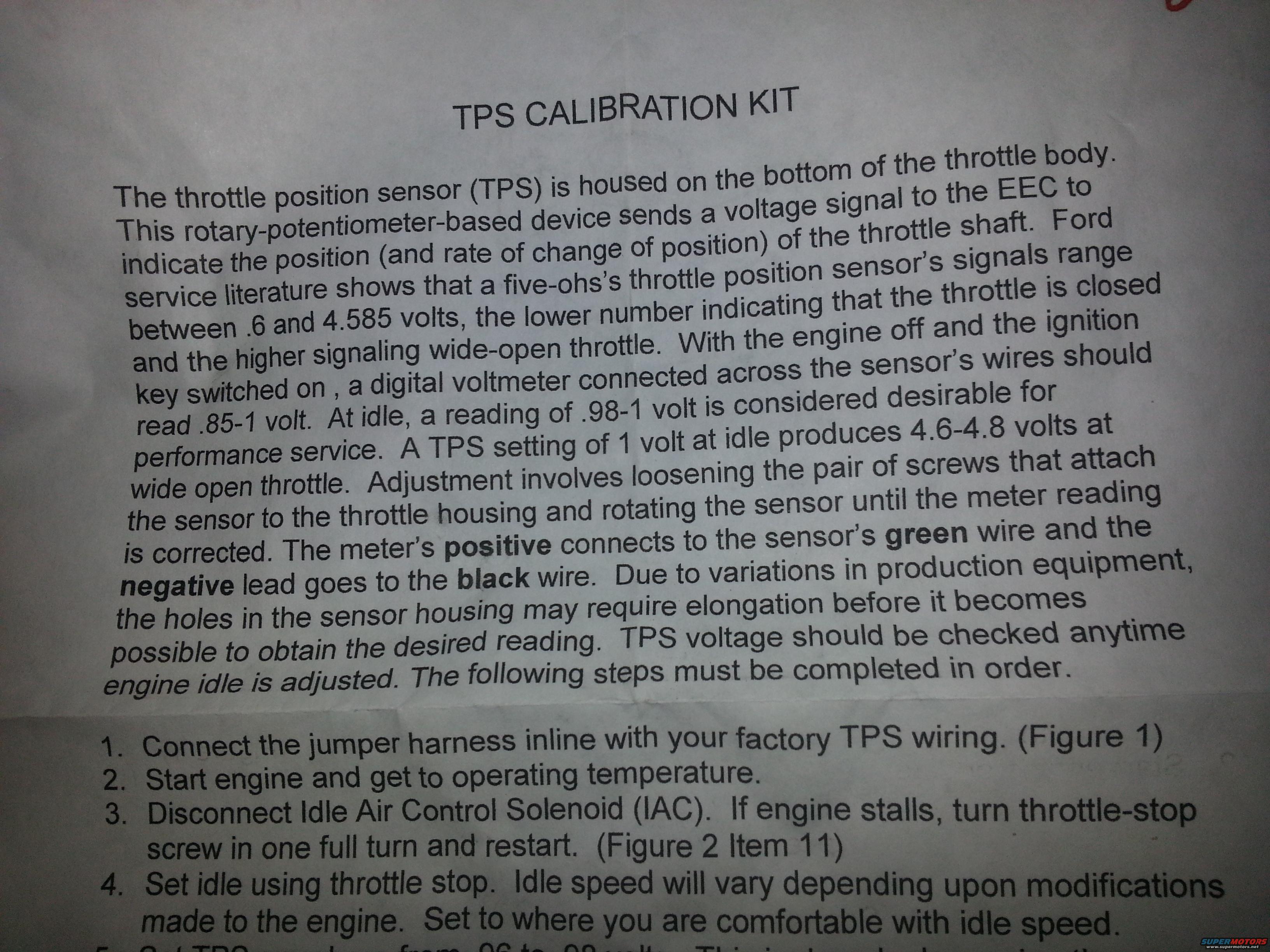
TPS calibration kit instruction page describing throttle position sensor operation, .6-4.585V signal range and idle adjustment to .98-1 volt by rotating the sensor on the throttle body.
Part of 1992-1996 Ford Bronco Service Procedures
This document is the first page of instructions for a Ford TPS (Throttle Position Sensor) Calibration Kit. It explains that the TPS is a rotary-potentiometer device mounted on the bottom of the throttle body that sends a voltage signal to the EEC computer indicating throttle position and rate of change. Per Ford service literature (referencing the 5.0 / "five-ohs" engine), the TPS signal ranges from .6 to 4.585 volts, with the low value at closed throttle and the high value at wide-open throttle. With the key on and engine off, the sensor should read .85-1 volt; an idle reading of .98-1 volt is desirable for performance service, and a 1-volt idle setting yields 4.6-4.8 volts at wide-open throttle. Adjustment involves loosening the two mounting screws and rotating the sensor; the meter's positive lead connects to the green wire and the negative to the black wire. Sensor mounting holes may need elongation to reach the desired reading, and TPS voltage should be rechecked whenever idle is adjusted. Numbered steps 1-4 (visible) cover installing the jumper harness inline with the factory TPS wiring, warming the engine, disconnecting the Idle Air Control (IAC) solenoid, and setting idle with the throttle-stop screw. Step 5 is cut off at the bottom of the scan.
Is this accurate? Sign in to help verify it.
Frequently asked questions
- What voltage range should a Ford 5.0 throttle position sensor read?
- Per the document, Ford service literature shows the TPS signal ranges between.6 and 4.585 volts, the lower number indicating closed throttle and the higher indicating wide-open throttle.
- What should the TPS read at idle for performance service?
- With engine off and key on, the sensor should read.85-1 volt across its wires; at idle, a reading of.98-1 volt is considered desirable for performance service. A 1-volt idle setting produces 4.6-4.8 volts at wide-open throttle.
- Which TPS wires do I connect the voltmeter to?
- The meter's positive lead connects to the sensor's green wire and the negative lead goes to the black wire.
- How do you adjust the TPS voltage?
- Loosen the pair of screws attaching the sensor to the throttle housing and rotate the sensor until the meter reading is corrected. Due to production variations, the holes in the sensor housing may require elongation to obtain the desired reading.
- What if the engine stalls when the IAC is disconnected during calibration?
- The instructions say to turn the throttle-stop screw in one full turn and restart the engine (Figure 2 Item 11).






No comments yet.