Ford Bronco Instrument Panel Support Bracket Kit - Repair Instructions
Reference · 1992-1996 BroncoAll 142 service procedures
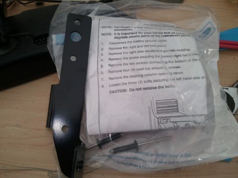











Step-by-step service procedure sheet for removing instrument panel components, listing numbered steps and a caution.
Part of 1992-1996 Ford Bronco Service Procedures
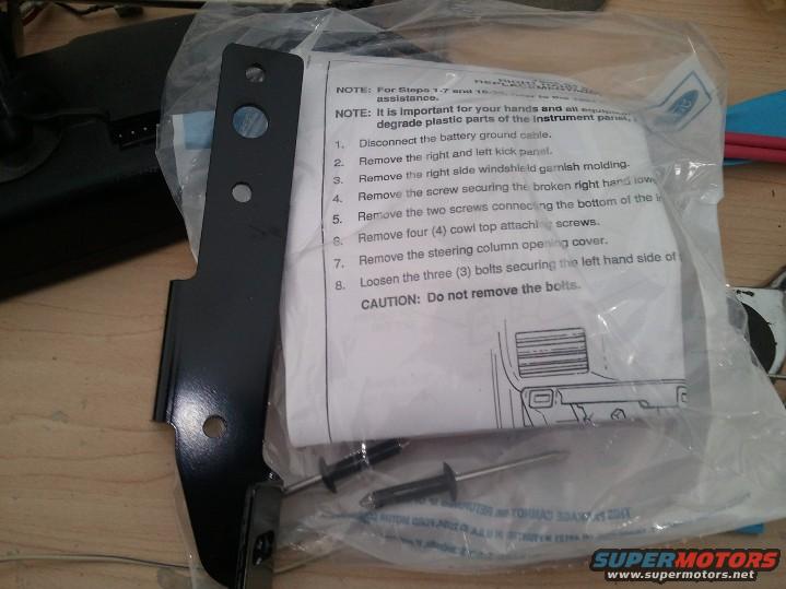
This photograph shows a Ford service/installation kit consisting of a black metal support bracket, two push-pin style fasteners, and a folded printed instruction sheet sealed inside a Ford plastic parts bag. The visible portion of the instruction sheet documents the first eight steps of a service procedure involving the instrument panel area, likely a dash or instrument panel support repair. The legible steps instruct the technician to disconnect the battery ground cable, remove the right and left kick panels, remove the right side windshield garnish molding, remove the screw securing the broken right-hand lower component, remove two screws at the bottom of the instrument panel, remove four cowl top attaching screws, remove the steering column opening cover, and loosen (but not remove, per the CAUTION) three bolts securing the left-hand side of the panel. Notes at the top reference additional steps (1-7 and 16 onward) and warn about care to avoid degrading plastic instrument panel parts. The sheet includes a line illustration of the dash/cowl area. The bag is marked that the package cannot be returned and is printed by Ford Motor Company in the U.S.A. The document header, part numbers, and remaining steps are obscured by folds and the bag.
Is this accurate? Sign in to help verify it.
Frequently asked questions
- What is the first step in this Ford instrument panel repair procedure?
- Step 1 is to disconnect the battery ground cable.
- How many cowl top attaching screws must be removed?
- Step 6 says to remove four (4) cowl top attaching screws.
- Should the three bolts on the left-hand side of the panel be removed?
- No. Step 8 says to loosen the three bolts, and a CAUTION explicitly states 'Do not remove the bolts.'
- What comes with this kit besides the instructions?
- The photo shows a black metal support bracket and two push-pin style fasteners packaged in a Ford plastic bag.
- What panels and trim need to be removed early in the procedure?
- The right and left kick panels, the right side windshield garnish molding, and the steering column opening cover.






No comments yet.