Home/
Registry/
Ford/
Bronco/
1992-1996/
“Eddie Bauer”/
Photo
supermotors.net/registry/media/1023943
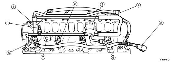
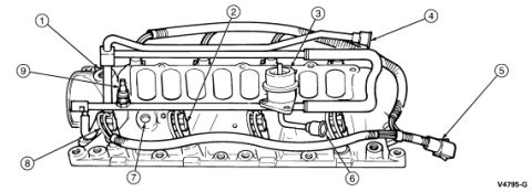
Ford Bronco Lower Intake Manifold Diagram - Component Callouts (V4795-G)
Reference · 1992-1996 BroncoAll 169 exploded parts diagrams
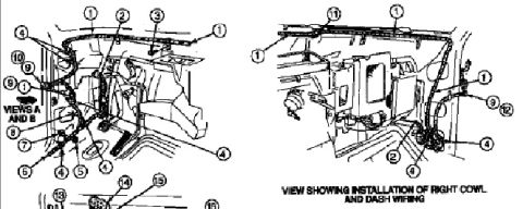
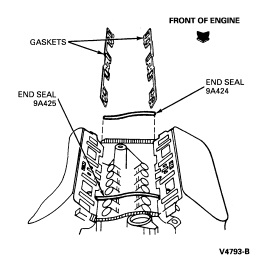
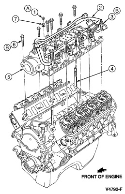
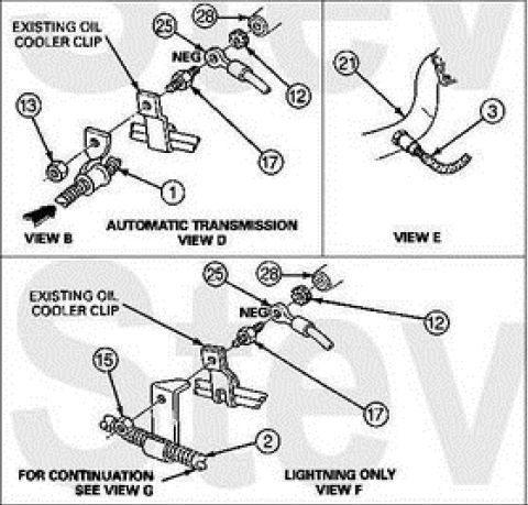


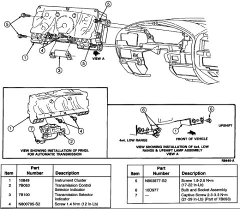
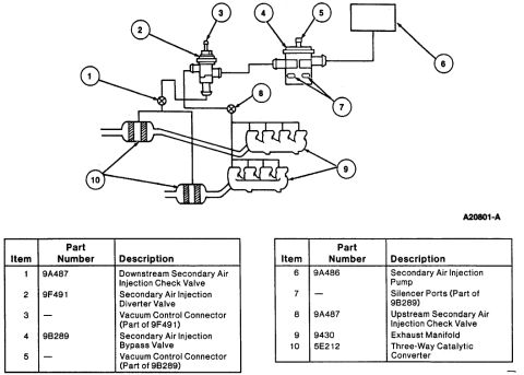










Exploded parts diagram of the intake manifold showing sensors, fittings and components with numbered callouts.
Part of 1992-1996 Ford Bronco Exploded Parts Diagrams
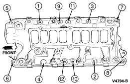
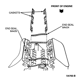
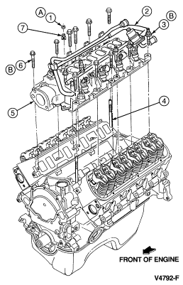
This document is a black-and-white line illustration showing a side view of an engine lower intake manifold assembly, apparently from a Ford service manual (figure code V4795-G). Nine numbered callout balloons (1 through 9) point to various components mounted on or attached to the manifold, including what appear to be sensors, fittings, vacuum/coolant hoses, a wiring harness with connector, and mounting points along the manifold flange. No legend, parts list, torque specifications, or descriptive text accompanies the illustration on this page, so the identity of each numbered item cannot be determined from this scan alone; the callout key presumably appears on an accompanying page. The file was uploaded to a 1994 Ford Bronco gallery as part of an album containing related engine and intake installation documents (intake gaskets, lower intake torque sequence, engine and intake installation), suggesting it is one page of a multi-page intake manifold removal/installation procedure. A reader can use this diagram to visually locate nine components associated with the lower intake manifold, provided they cross-reference the numbered callouts with the legend from the companion pages in the same document set.
Is this accurate? Sign in to help verify it.
Frequently asked questions
- What does this diagram show?
- A side-view line illustration of a lower intake manifold assembly with nine numbered callout balloons (1-9) pointing to components on and around the manifold. Figure code V4795-G appears at lower right.
- Does this page identify what each numbered callout is?
- No. The scan contains only the callout numbers 1 through 9 and the figure code V4795-G; there is no legend or parts list on this page, so the callout key must be on an accompanying page.
- Are any torque values or part numbers listed on this page?
- No. No torque specifications, part numbers, or text labels are visible on this illustration, only callout numbers and the figure code V4795-G.
- What is the figure reference code on this diagram?
- V4795-G, printed at the upper/lower right corner of the illustration.






No comments yet.