Home/
Registry/
Ford/
Bronco/
1992-1996/
“Eddie Bauer”/
Photo
supermotors.net/registry/media/1023944
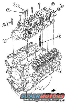
1994 Ford Bronco V8 Engine & Intake Manifold Installation Exploded Diagram
Reference · 1992-1996 BroncoAll 169 exploded parts diagrams
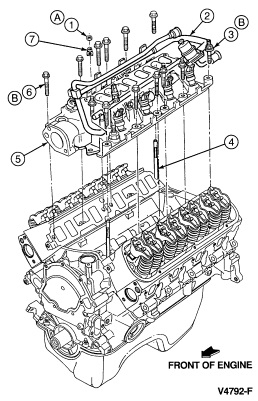
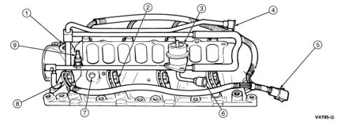
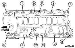
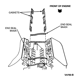
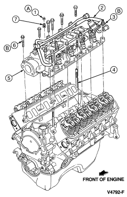


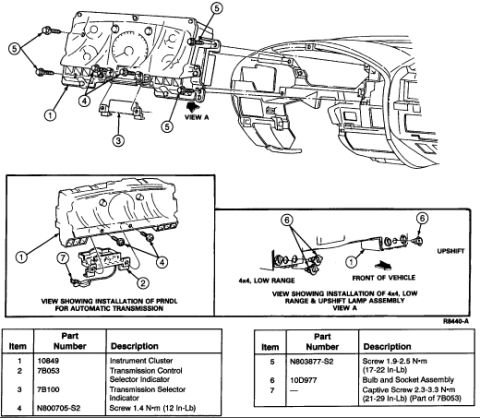
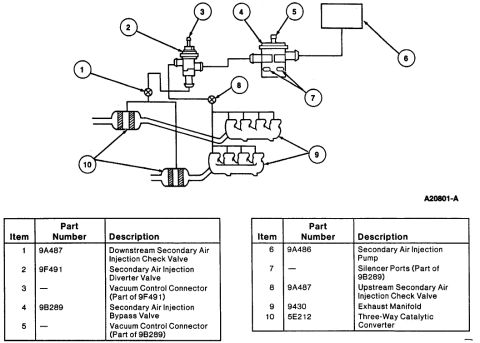










Exploded parts diagram of the engine intake manifold and cylinder head assembly with numbered callouts.
Part of 1992-1996 Ford Bronco Exploded Parts Diagrams
This document is an exploded parts diagram showing the installation relationship of intake components on a V8 engine. The illustration depicts the engine long block at the bottom with the valley/lifter area, rocker arms, and cylinder heads visible, and above it, separated in exploded fashion, the intake manifold assembly and related hardware. Numbered callouts 1, 3, 4, 5, 6, and 7 identify individual parts such as bolts, studs, and manifold components, while lettered callouts A and B flag specific fasteners or reference points (B appears in two locations). An arrow marked 'FRONT OF ENGINE' establishes orientation, and the figure carries the Ford illustration reference number V4792-F. No legend, torque specifications, or part numbers accompany the callouts on this page, the numbered items would be identified in an accompanying text or table not included in this scan. The diagram is useful for understanding bolt locations and the order/orientation in which the intake manifold and its fasteners install onto the engine. It was uploaded as part of an album covering intake gasket and lower intake torque sequence documentation for a 1994 Ford Bronco.
Is this accurate? Sign in to help verify it.
Frequently asked questions
- What does this diagram show?
- An exploded view of an engine with the intake manifold assembly and its fasteners separated above the block, with numbered callouts (1, 3, 4, 5, 6, 7) and lettered callouts (A, B) identifying components, plus a 'FRONT OF ENGINE' orientation arrow.
- Does the diagram include torque specifications or a parts legend?
- No. Only the callout numbers/letters, the 'FRONT OF ENGINE' arrow, and the figure reference V4792-F are visible; no legend or torque values appear on this page.
- What is the illustration reference number for this diagram?
- V4792-F, printed in the lower right corner.
- How is the engine oriented in the diagram?
- An arrow labeled 'FRONT OF ENGINE' at the lower right indicates the front of the engine faces toward the lower right of the illustration.






No comments yet.