Home/
Registry/
Ford/
Bronco/
1992-1996/
“Eddie Bauer”/
Photo
supermotors.net/registry/media/1023945
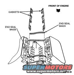
Ford Bronco Intake Manifold Gasket & End Seal Diagram (9A424, 9A425)
Reference · 1992-1996 BroncoAll 169 exploded parts diagrams
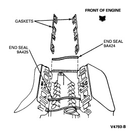
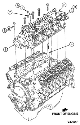
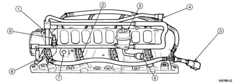
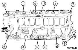
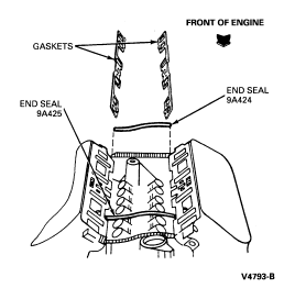












Exploded parts diagram showing intake manifold gaskets and end seals positioned on the engine block.
Part of 1992-1996 Ford Bronco Exploded Parts Diagrams
This document is an exploded parts diagram showing the placement of intake manifold gaskets and end seals on a V-configuration engine, uploaded to the gallery of a 1994 Ford Bronco. The illustration shows the engine block/cylinder heads from above with two intake manifold gaskets (labeled 'GASKETS') positioned over the intake ports on each cylinder head. Two rubber end seals are identified by Ford base part numbers: end seal 9A425 at the front of the engine valley and end seal 9A424 at the rear. A 'FRONT OF ENGINE' orientation arrow is provided at the top right to help the installer position the components correctly. The figure number V4793-B appears at the bottom right, indicating this is a Ford service illustration. The diagram contains no torque values, sequence numbers, or year/model callouts, it is purely a component location/orientation reference for intake gasket and end seal installation, likely part of a multi-page intake manifold installation procedure (companion pages in the album include torque sequence and installation instructions).
Is this accurate? Sign in to help verify it.
Frequently asked questions
- What part numbers are shown for the intake manifold end seals?
- The diagram labels two end seals: 9A425 at the front of the engine and 9A424 at the rear.
- Which end seal goes at the front of the engine?
- End seal 9A425 is shown toward the front of the engine (indicated by the 'FRONT OF ENGINE' arrow), while end seal 9A424 is at the opposite end.
- What components does this diagram show being installed?
- It shows two intake manifold gaskets positioned over the cylinder heads and two end seals (9A425 and 9A424) placed across the front and rear of the engine block valley.
- Does this diagram include torque specifications?
- No. It is a placement/orientation diagram only; no torque values or tightening sequence are shown (figure V4793-B).






No comments yet.