SuperMotors SuperMotors SUPERMOTORS Search: try “orange Bronco on 35s”
Home/ Registry/ Ford/ Bronco/ 1992-1996/ “pukin' dogII”/ Photo supermotors.net/registry/media/102649

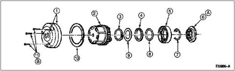
Locking hub exploded parts diagram with callouts 1-11, A and B,…
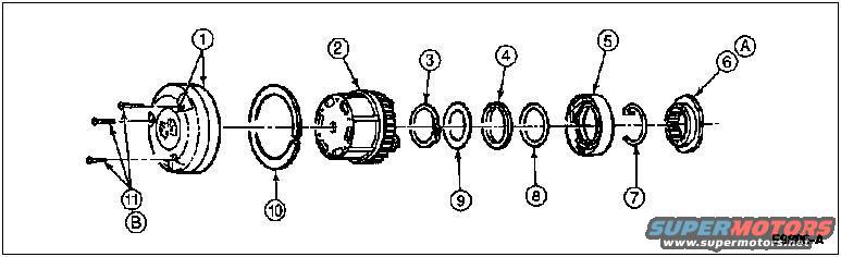
Locking hub exploded parts diagram with callouts 1-11, A and B, figure E9606-A
Locking hub exploded parts diagram with callouts 1-11, A and B, figure E9606-AOriginal file
Locking hub exploded parts diagram with callouts 1-11, A and B, figure E9606-A

Reference · 1992-1996 BroncoAll 169 exploded parts diagrams
Ford E4OD Transmission Seals, Rings & Gaskets Exploded Diagram (D16539-A) 1996 Ford Bronco Front Driveshaft Exploded Parts Diagram - Assembly View 1996 Ford Bronco 5.0L/5.8L Muffler & Exhaust Hanger Exploded Diagram (U3395-A) Locking hub exploded parts diagram with callouts 1-11, A and B, figure E9606-A Ford Dual Air Horn Kit 13800 Exploded Parts Diagram - D7HZ-13800-A 1996 Ford Bronco Manual Locking Hub Cap & Lock Ring Diagram - Torque Spec 1992-96 Ford Bronco Instrument Panel & Pad Exploded Parts Diagram (04320, 04292) 1996 Ford Bronco Instrument Panel Wiring Harness Location Diagram (K17295-C) 1996 Ford Bronco/F-150 Distributor Exploded Parts Diagram & Installation 03-07A-6 Ford Bronco Front Coil Spring & Shock Absorber Exploded Diagram (F2858-Q) Ford Bronco/F-Series Engine Block Ground Cable Diagram - Neg Battery Cable Views Instrument panel 04320 exploded view with finish panel 044D70, headlamp switch knob 11666 and mouldings 169exploded parts diagrams1992-1996 Ford Bronco More reference Ford TSB 88-5-14 Oil Pressure Switch & Resistor Jumper Wiring DiagramWiring diagram Parasitic Battery Draw Test Procedure - Checking for Unwanted Draw (Wilson)Service procedure Ford Bronco/F-Series Axle Code Chart - Certification Label Rear Axle RatiosSpec plate 1996 Ford Bronco Owner's Manual - Checking & Adding Engine CoolantManual page 1996 Ford Bronco Secondary Air Injection (Thermactor) System Diagram - TAB/TADSchematic 1996 Ford Bronco/F-150 Frame Dimensions - Underbody Misalignment Check DiagramBlueprint 1992-96 Ford F150 F250 Bronco Dashboard Components Parts Diagram - LMC TruckBrochure 1996 Ford Bronco A/C-Heater Vacuum Routing Diagram - HVAC Door Vacuum MotorsVacuum routing 1996 Ford Bronco Power Distribution Box Diagram - Fuel Pump & PCM RelaysFuse chart Rod Bolt Stretch Monitoring Chart - 8-Rod V8 Connecting Rod Bolt Record SheetTorque spec

Auto Lock Hubs D44 1996
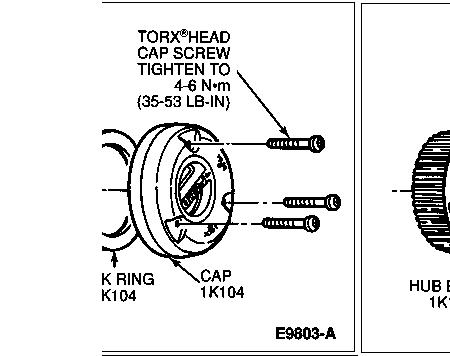
1 Cap, 2 Hub Body, 3 Snap Ring, 4 Plastic Thrust Washer, 5 Cam Assembly (Part of 1K105), 6 Wheel Retainer (Nut), 7 Wheel Retainer Key, 8 Steel Thrust Washer, 9 Splined Thrust Washer, 10 Lock Ring, 11 cap screws (3)
A. While Rotating Front Disc Brake Hub & Rotor, Tighten Wheel Retainer (Nut) to 68 N-m (50 Lb-Ft) to Seat Wheel Bearings. Back Nut Off 90 Degrees (1/4 Turn). Tighten to 1.8 N-m (16 Lb-In).
B. Tighten to 4-6 N-m (35-53 Lb-In)

Removal
1 Separate cap from body assembly by removing the three capscrews, using Torx® bit TX25 or equivalent, from the cap.
2 Remove cap.
3 Remove the lock ring seated in the groove of the front disc brake hub and rotor (1102).
4 Remove the body assembly from the front disc brake hub and rotor.
5 Remove C-washer or snap ring from stub shaft groove.
6 Remove spacers (three thrust washers) from shaft.
7 Remove cam assembly. Pull to remove.
8 If front disc brake hub and rotor and front wheel spindle (3105) are to be removed, refer to Wheel Grease Seal and Bearing, Front Replacement and Repacking in the Disassembly and Assembly portion of this section.

Part of 1992-1996 Ford Bronco Exploded Parts Diagrams

Owner caption · Photo 4 of 221

Is this accurate? Sign in to help verify it.

Comments

No comments yet.

More 1992-1996 Broncos