Home/
Registry/
Ford/
Bronco/
1992-1996/
“pukin' dogII”/
Photo
supermotors.net/registry/media/877798
1996 Ford Bronco Front Driveshaft Exploded Parts Diagram - Assembly View

Reference · 1992-1996 BroncoAll 169 exploded parts diagrams
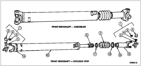
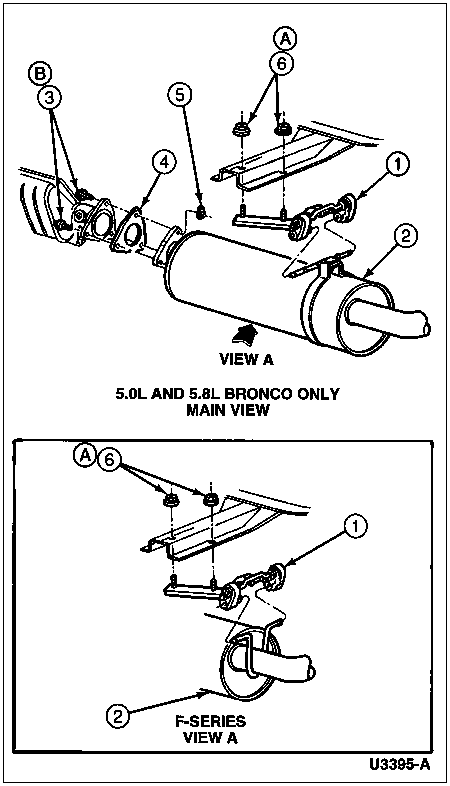
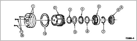
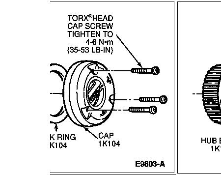












Assembled and exploded view drawing of the front driveshaft with numbered part callouts.
Part of 1992-1996 Ford Bronco Exploded Parts Diagrams
This document is a two-part line-art illustration of a front driveshaft. The upper drawing, labeled "FRONT DRIVESHAFT: ASSEMBLED," shows the complete driveshaft with yokes at each end, the shaft tube, and a flexible boot/CV section near the right end. The lower drawing, labeled "FRONT DRIVESHAFT: EXPLODED VIEW," separates the assembly into its individual components identified by numbered callouts 1 through 13. Callouts 1-5 appear at both ends of the shaft, pointing to universal joint components such as the U-joint cross, bearing cups, snap rings/clips, and small hardware. Callout 13 points to the left-end yoke, 12 to the main shaft tube, 6 to the splined slip section, 11 to a small ring/washer, 7 to the flexible boot, 10 to a retaining ring/clamp area, 9 to a washer/seal, and 8 to the right-end slip yoke. The figure carries the reference code E5581-C in the lower right corner. No parts legend, part numbers, torque specifications, or year/model applicability text is printed on this scan; it serves purely as a visual exploded-parts reference for identifying front driveshaft components and their assembly order.
Is this accurate? Sign in to help verify it.
Frequently asked questions
- What does this diagram show?
- It shows a front driveshaft in two views: one fully assembled and one exploded view with numbered callouts 1 through 13 identifying the individual components.
- How many numbered components are identified in the exploded view?
- Thirteen numbered callouts (1-13) are shown, with callouts 1-5 repeated at both ends of the driveshaft for the U-joint hardware.
- Does the diagram include part numbers or a parts legend?
- No. Only the numbered callouts, the labels 'FRONT DRIVESHAFT: ASSEMBLED' and 'FRONT DRIVESHAFT: EXPLODED VIEW,' and the figure reference code E5581-C are printed on the document.
- What is the figure reference code on this illustration?
- E5581-C, printed in the lower right corner of the diagram.






No comments yet.