Home/
Registry/
Ford/
Bronco/
1992-1996/
“pukin' dogII”/
Photo
supermotors.net/registry/media/877845
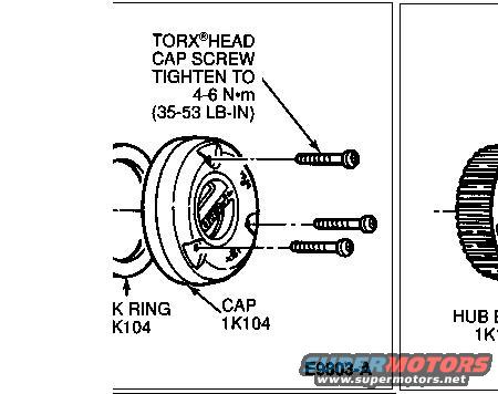
1996 Ford Bronco Manual Locking Hub Cap & Lock Ring Diagram - Torque Spec
Reference · 1992-1996 BroncoAll 169 exploded parts diagrams
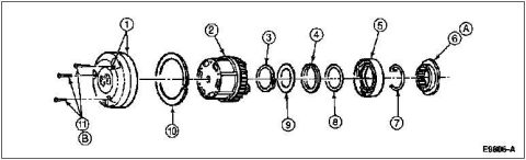
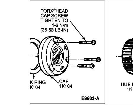












Hub cap and ring assembly drawing showing Torx head cap screws with a 35-53 lb-in tightening note.
Part of 1992-1996 Ford Bronco Exploded Parts Diagrams
This is a cropped scan of a factory-style exploded parts diagram showing a manual locking hub assembly, uploaded to accompany a 1996 Ford Bronco. The visible left panel illustrates the hub lock cap and lock ring, with three Torx head cap screws shown being inserted into the cap. A callout specifies the torque for the Torx head cap screws: tighten to 4-6 N·m (35-53 lb-in). Component callouts identify the CAP (part reference 1K104) and a lock ring (label partially cut off at the left edge, appearing as "K RING / K104"). The diagram carries the Ford illustration reference number E9803-A. A second panel on the right side is mostly cropped out of frame, showing part of a splined hub component labeled "HUB B..." (truncated). From this document, a reader can learn the correct fastener torque specification for reinstalling the manual hub lock cap screws and the basic component relationship between the cap, lock ring, and hub body during manual locking hub service or disassembly.
Is this accurate? Sign in to help verify it.
Frequently asked questions
- What is the torque spec for the Torx head cap screws on the manual locking hub cap?
- Tighten the Torx head cap screws to 4-6 N·m (35-53 lb-in).
- What type of screws hold the manual hub lock cap on?
- Torx head cap screws, three are shown in the diagram.
- What is the part reference for the hub lock cap?
- The cap is labeled with reference 1K104 in the diagram.
- What components are shown in this hub diagram?
- The visible portion shows the cap (1K104), a lock ring (label partially cut off, appearing as K RING / K104), three Torx head cap screws, and part of a hub body in a second cropped panel.






No comments yet.