Home/
Registry/
Ford/
Bronco/
1992-1996/
“pukin' dogII”/
Photo
supermotors.net/registry/media/877832
1996 Ford Bronco Instrument Panel Wiring Harness Location Diagram (K17295-C)

Reference · 1992-1996 BroncoAll 169 exploded parts diagrams
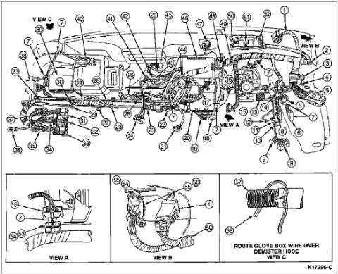







Instrument panel wiring harness routing diagram with numbered connector and routing callouts and Views A, B and C detail insets.
Part of 1992-1996 Ford Bronco Exploded Parts Diagrams
This document is a scanned exploded-parts / component-location illustration of a Ford truck instrument panel (dash) wiring harness area, drawing number K17295-C. The main illustration shows the dash from behind with numbered callouts 1 through roughly 51 pointing to harness connectors, modules, wiring runs, retainers, and mounting points across the instrument panel, with arrows indicating the locations of three detail views (VIEW A, VIEW B, VIEW C). Three inset detail views along the bottom enlarge specific areas: VIEW A (callouts 7, 15, 33, 52, 53) shows a harness/connector detail on the left side of the dash; VIEW B (callouts 1, 7, 50, 54, 55, 56) shows a convoluted harness routing with connectors near the right side; VIEW C (callouts 57, 58) shows a corrugated demister hose with the instruction 'ROUTE GLOVE BOX WIRE OVER DEMISTER HOSE.' No legend or parts list identifying the numbered items is included on this page, so the reader can locate components spatially but cannot identify part names or numbers from this sheet alone. The uploader filed it as showing the air bag module location on a 1996 Ford Bronco; no year, model, or part identification text appears on the drawing itself.
Is this accurate? Sign in to help verify it.
Frequently asked questions
- What does this diagram show?
- It is an exploded/location illustration of the instrument panel (dash) area showing a wiring harness with numbered callouts (1 through about 51) and three enlarged detail views labeled VIEW A, VIEW B, and VIEW C.
- Is there a legend identifying the numbered callouts?
- No. The page contains only the numbered callouts and view labels; no parts list or key naming the components is included on this sheet.
- What routing instruction is given in VIEW C?
- VIEW C instructs: 'ROUTE GLOVE BOX WIRE OVER DEMISTER HOSE,' with callouts 57 and 58 pointing to the wire and hose.
- What is the drawing reference number on this document?
- The illustration carries the reference number K17295-C in the lower right corner.
- Which callouts appear in the detail views?
- VIEW A shows callouts 7, 15, 33, 52 and 53; VIEW B shows callouts 1, 7, 50, 54, 55 and 56; VIEW C shows callouts 57 and 58.






No comments yet.