Home/
Registry/
Ford/
Bronco/
1992-1996/
“pukin' dogII”/
Photo
supermotors.net/registry/media/877793
1996 Ford Bronco 5.0L/5.8L Muffler & Exhaust Hanger Exploded Diagram (U3395-A)

Reference · 1992-1996 BroncoAll 169 exploded parts diagrams
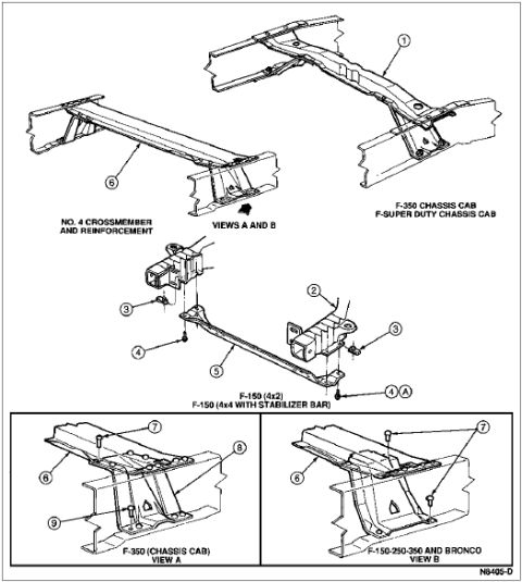
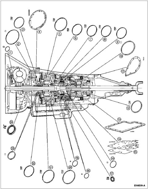
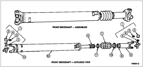
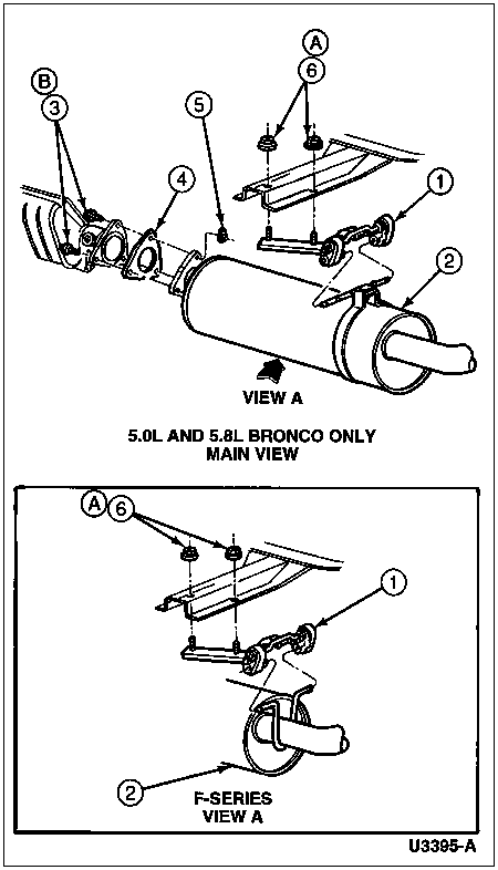












Assembly drawing of the exhaust muffler and hangers with numbered part callouts for Bronco and F-Series.
Part of 1992-1996 Ford Bronco Exploded Parts Diagrams
This document is an exploded parts diagram (Ford illustration number U3395-A) showing the rear exhaust/muffler assembly and its mounting hardware. The main view is labeled "5.0L AND 5.8L BRONCO ONLY" and depicts the muffler (callout 2) connecting to the exhaust pipe/catalytic converter section via a flange and gasket (callouts 3 and 4), with a hanger/inlet pipe assembly (callout 1) attached to the frame with insulators and fasteners (callouts 5 and 6, area A). A second inset, labeled "F-SERIES VIEW A," shows the corresponding hanger arrangement (callouts A, 6, 1) and tailpipe/muffler outlet (callout 2) for F-Series trucks. The diagram uses lettered detail references (A, B) and numbered callouts but does not include a parts legend, part numbers, or torque specifications on this page, those are presumably on a companion page. A reader can learn how the muffler, gasket, hangers, and mounting insulators fit together on 5.0L/5.8L Broncos and how the F-Series hanger differs, which is useful for muffler replacement or exhaust hanger repair.
Is this accurate? Sign in to help verify it.
Frequently asked questions
- Which vehicles does the main view of this exhaust diagram apply to?
- The main view is labeled "5.0L AND 5.8L BRONCO ONLY," so it applies to Broncos with the 5.0L or 5.8L engine.
- Does this diagram cover F-Series trucks too?
- Yes, a separate inset labeled "F-SERIES VIEW A" shows the muffler hanger and mounting hardware arrangement for F-Series trucks.
- Does the diagram list part numbers or a legend for the callouts?
- No. The diagram uses numbered callouts (1-6) and lettered references (A, B), but no legend, part numbers, or torque values appear on this page. The only identifier is the illustration number U3395-A.
- What components are shown in the diagram?
- It shows the muffler, the connecting exhaust pipe flange and gasket, the hanger/support brackets, and the insulators and fasteners that mount the assembly to the frame, identified by callouts 1 through 6.






No comments yet.