Home/
Registry/
Ford/
Bronco/
1992-1996/
“Eddie Bauer”/
Photo
supermotors.net/registry/media/1030296
2002 Ford Expedition Headlight Wiring Diagram - Autolamp & Headlamp Relay (Top)
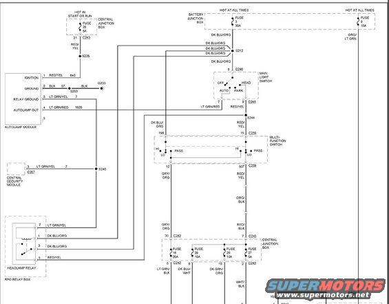
Wiring diagram detail of headlamp and multi-function switch circuits with color-coded wires and connectors.
Part of 1992-1996 Ford Bronco Wiring Diagrams
This document is the top half of a headlight circuit wiring diagram (uploaded as '2002 expedition headlight circuit top.jpg'). It shows power distribution from the Battery Junction Box (Fuse 3, 30A and Fuse 9, 15A, both hot at all times) and the Central Junction Box (Fuse 29, 5A, hot in start or run) to the exterior lighting system. Major components depicted include the Autolamp Module (pins 1-5 with ignition, ground, relay ground, and autolamp out circuits 640, 57, 7, and 1525), the Central Security Module (connector C257), the Main Light Switch with OFF/AUTO/PARK/HEAD positions (connector C246), the Multi-Function Switch with HI/LO/PASS contacts (connector C259), and the Headlamp Relay in the RPO Relay Box. The lower Central Junction Box section shows Fuse 16 (20A), Fuse 28 (10A), Fuse 26 (10A), and Fuse 27 (5A) feeding LT GRN/BLK, DK BLU/WHT, DK GRN/ORG, and WHT/BLK output wires. Wire colors (DK BLU/ORG, RED/YEL, LT GRN/YEL, GRY/ORG, ORG/BLK, RED/BLK, etc.), splice points (S203, S212, S225, S244, S245), ground G200, and connector pin numbers are all identified, making this useful for diagnosing headlamp, autolamp, and flash-to-pass circuit issues.
Is this accurate? Sign in to help verify it.
Frequently asked questions
- What fuse powers the headlight circuit from the Battery Junction Box?
- Fuse 3, a 30A fuse in the Battery Junction Box (hot at all times), feeds DK BLU/ORG wires through splice S212 to the Main Light Switch and headlamp relay circuits. Fuse 9 (15A, hot at all times) feeds an ORG/LT GRN circuit.
- What are the Autolamp Module pin assignments?
- Pin 1: Ignition (RED/YEL, circuit 640); Pin 2: Ground (BLK, circuit 57, through S203 to G200); Pin 3: Relay Ground (LT GRN/YEL, circuit 7); Pin 4: Autolamp Out (LT GRN/RED, circuit 1525); Pin 5 is shown unlabeled.
- Which fuses in the Central Junction Box are shown in this diagram?
- Fuse 29 (5A, hot in start or run), Fuse 16 (20A, output LT GRN/BLK), Fuse 28 (10A, output DK BLU/WHT), Fuse 26 (10A, output DK GRN/ORG), and Fuse 27 (5A, output WHT/BLK).
- What positions does the Main Light Switch have and what wires connect to it?
- The Main Light Switch has OFF, AUTO, PARK, and HEAD positions. It receives DK BLU/ORG power on pin 8 (C246) and outputs LT GRN/RED on pin 7 and RED/YEL on pin 9 (C246).
- What wire colors come out of the Multi-Function Switch for the headlights?
- The Multi-Function Switch (HI/LO/PASS contacts) outputs GRY/ORG on pin 12 and RED/YEL on pin 507 (C259), the latter continuing as ORG/BLK and then RED/BLK to Central Junction Box pin 7 (C243).
Comments
More from this build







No comments yet.