Home/
Registry/
Ford/
Bronco/
1992-1996/
“Eddie Bauer”/
Photo
supermotors.net/registry/media/1078367
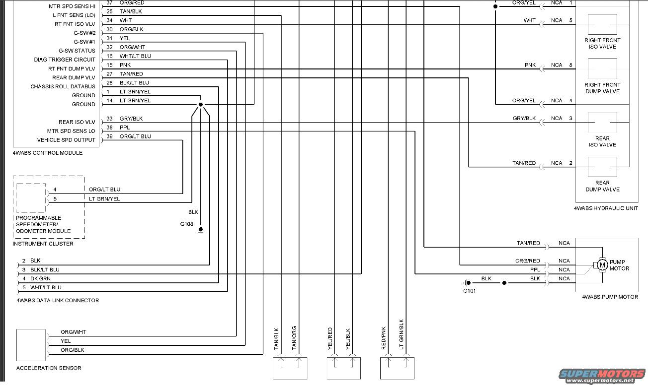
Ford Bronco 4WABS ABS Wiring Diagram - Control Module Pinout & Wire Colors
Reference · 1992-1996 BroncoAll 411 wiring diagrams
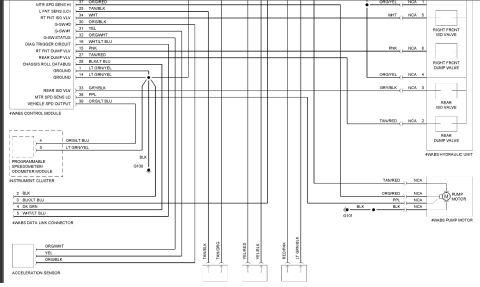
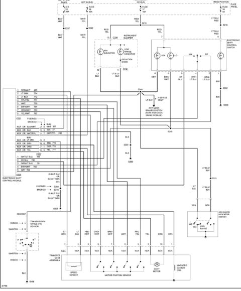
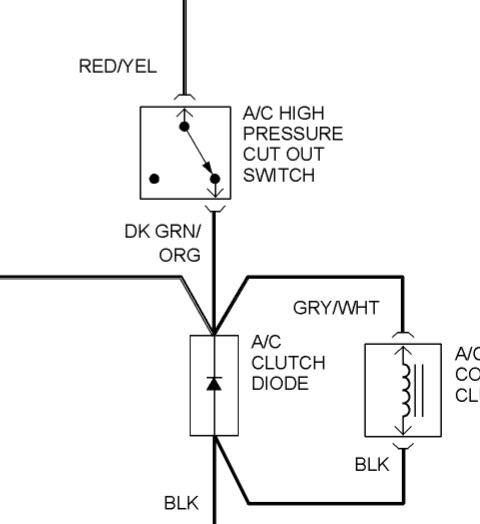
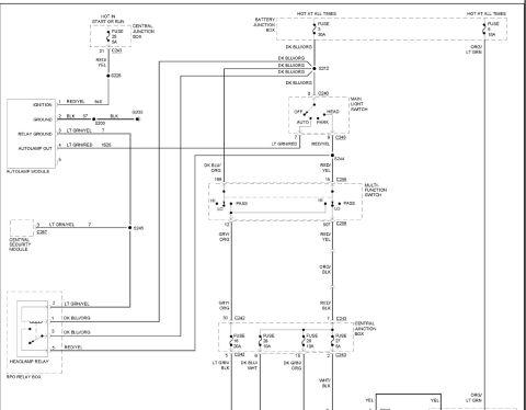














Wiring diagram for a 4-wheel ABS control module showing valves, pump motor, sensors, and color-coded wires.
Part of 1992-1996 Ford Bronco Wiring Diagrams
This document is a wiring diagram for the Four-Wheel Anti-lock Brake System (4WABS) on a mid-1990s Ford Bronco. It shows the 4WABS control module with numbered connector pins and their functions and wire colors, including motor speed sense high/low (pins 37 ORG/RED, 38 PPL), left front sensor low (25 TAN/BLK), right front ISO valve (34 WHT), G-switches #1/#2 and status (31 YEL, 30 ORG/BLK, 32 ORG/WHT), diagnostic trigger circuit (16 WHT/LT BLU), right front dump valve (15 PNK), rear dump valve (27 TAN/RED), chassis roll databus (28 BLK/LT BLU), grounds (1 and 14, LT GRN/YEL to ground G108), rear ISO valve (33 GRY/BLK), and vehicle speed output (39 ORG/LT BLU). Connections are shown to the programmable speedometer/odometer module in the instrument cluster (pins 4 and 5), the 4WABS data link connector (pins 2-5), the acceleration sensor (ORG/WHT, YEL, ORG/BLK), the 4WABS hydraulic unit (right front and rear ISO and dump valves with pins 1-8, all circuits marked NCA), and the 4WABS pump motor with its ground at G101. A reader can use this to trace ABS wiring by pin number and wire color for diagnostics.
Is this accurate? Sign in to help verify it.
Frequently asked questions
- What wire color is the rear ISO valve circuit on the 4WABS control module?
- Pin 33 of the 4WABS control module, labeled REAR ISO VLV, uses a GRY/BLK wire, which connects to pin 3 (circuit NCA) at the 4WABS hydraulic unit's rear ISO valve.
- Which pins on the 4WABS control module are grounds?
- Pins 1 and 14 are both grounds, using LT GRN/YEL wires that splice together and go to ground G108 via a BLK wire.
- What are the pinouts of the 4WABS data link connector?
- Pin 2 is BLK, pin 3 is BLK/LT BLU, pin 4 is DK GRN, and pin 5 is WHT/LT BLU.
- Where does the 4WABS pump motor get its ground?
- The pump motor grounds through a BLK wire to ground point G101.
- What wires connect the ABS module to the instrument cluster speedometer module?
- The programmable speedometer/odometer module in the instrument cluster connects via pin 4 (ORG/LT BLU, vehicle speed output from module pin 39) and pin 5 (LT GRN/YEL).






No comments yet.