Home/
Registry/
Ford/
Bronco/
1978-1979/
1979 Ford Bronco/
Photo
supermotors.net/registry/media/1032649
1979 Ford Bronco/F100-F350 Fuel & Temperature Gauge Troubleshooting Diagram
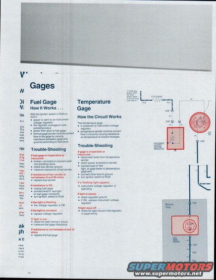
Fuel gage how-it-works and troubleshooting: instrument voltage regulator outputs ~5V pulsating; fuel sender resistance must be 8-66 ohms and gage 8-16 ohms, with test-light diagnostic steps.
This is page 30 of a Ford factory-style trouble-shooting guide covering the 1979 Bronco and F100 through F350 trucks, focused on the instrument panel gages. The 'Gages' section explains how the fuel gage works: with the ignition in RUN or ACCY, power flows to an instrument voltage regulator that averages a 5-volt pulsating output to the fuel gage, and the fuel sender varies resistance according to float level. Trouble-shooting steps cover an inoperative or inaccurate fuel gage: check for broken/corroded wires, verify sender ground, and measure sender resistance (replace the sender if not between 8 and 86 ohms). Test-light diagnosis at the fuel gage connector identifies whether the voltage regulator, wiring, or gage itself (8-16 ohms spec) is at fault. The temperature gage section explains that the temperature sender varies resistance with coolant temperature, with similar test-light diagnostics for the instrument voltage regulator. A wiring diagram on the right shows the circuit from splice S303 (hot in RUN and ACCY) through an 8-to-9-ohm resistance, connectors C208, C308, and C306, the instrument cluster voltage regulator, fuel gage, and the 'Bronco Only' fuel gage sender grounding through splice S805 to ground G701, with wire colors bk/gr, PC, o, bl, and bk noted.
Is this accurate? Sign in to help verify it.
Frequently asked questions
- What is the correct resistance range for the fuel gauge sender on a 1979 Ford Bronco or F-Series truck?
- The document states the fuel sender resistance should be between 8 and 86 ohms; if it is not, replace the fuel sender.
- What resistance should the fuel gauge itself measure?
- The fuel gage resistance should be between 8 and 16 ohms; if not, replace the fuel gage.
- How does the fuel gauge circuit work?
- With the ignition switch in RUN or ACCY, power goes to an instrument voltage regulator that averages a 5-volt pulsating output. Power then goes to the fuel gage, and the fuel gage sender controls current flow by varying resistance between gage and ground according to float level.
- How do I test whether the instrument voltage regulator is working?
- Unplug the fuel gage, connect a test light lead to the fuel gage connector, and turn the ignition to RUN. If the light flashes, the voltage regulator is OK; if the light is constant, replace the voltage regulator; if the light is out, check for open wiring and measure fuel gage resistance.
- Why is my temperature gauge inaccurate or not working?
- Disconnect the wires from the temperature sender, check power available to the sender, connect a test light or gage tester to the temperature gage wire with the other lead grounded, and turn the ignition to RUN. A flashing light means the instrument voltage regulator is operating; a steady light means check the regulator ground and replace the regulator if OK; no light means check for an open circuit in the regulator or gage wiring.
Comments
More from this build







No comments yet.