Home/
Registry/
Ford/
Bronco/
1987-1991/
“Eddie Bauer”/
Photo
supermotors.net/registry/media/1046656
1995 Ford Bronco Warning Chime Wiring Diagram (66-1) - Seat Belt & Key Buzzer

Reference · 1987-1991 BroncoAll 175 wiring diagrams


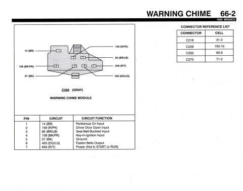
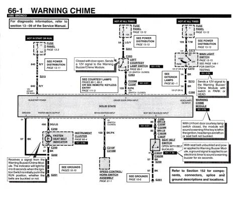
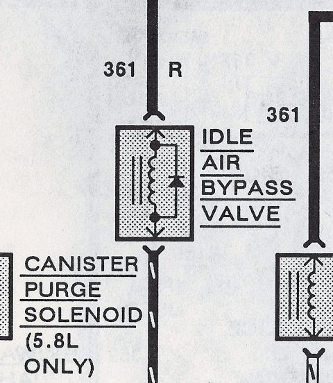
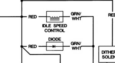












Wiring diagram of the warning chime circuit showing fuse panels, switches, the chime module and color-coded wires.
Part of 1987-1991 Ford Bronco Wiring Diagrams
This is page 66-1 of the 1995 Ford Bronco electrical and vacuum troubleshooting manual (EVTM), showing the Warning Chime circuit wiring diagram. It documents the solid-state Warning Chime Module with its seven pins: run/start power (pin 7), driver door open input (pin 2), headlamps on input (pin 1), ground (pin 5), fasten belts output (pin 6), key-in-ignition input (pin 4), and seat belt buckled input (pin 3). Power sources are fuse 17 (10A, hot in start or run, circuit 640 R/Y), fuse 8 (15A, hot at all times, circuit 54 LG/Y through the left courtesy lamp switch and circuit 159 R/PK), and fuse 4 (15A, hot at all times, circuit 195 T/W through the main light switch and circuit 14 BR). Downstream circuits include the fasten seat belt indicator in the instrument cluster (circuit 450 DG/LG), key-in-ignition sensing via circuit 158 BK/PK to the speed control/horn switch assembly, and seat belt switch input via circuit 85 BR/LB. Grounds are at G201 via circuit 57 BK through splices S200 and S202. Connectors identified include C250, C263, C273, C280, C229M/F, C302M/F, and C219F/M. Callouts explain chime behavior: warnings for key-in-ignition, headlamps on, or seat belt unbuckled with door open, and a six-second buzzer for unbuckled belts.
Is this accurate? Sign in to help verify it.
Frequently asked questions
- What fuses power the warning chime module on a 1995 Bronco?
- Fuse 17 (10A, hot in start or run) via circuit 640 R/Y, fuse 8 (15A, hot at all times) via circuit 54 LG/Y through the left courtesy lamp switch, and fuse 4 (15A, hot at all times) via circuit 195 T/W through the main light switch.
- What are the pin functions on the 1995 Bronco warning chime module?
- Pin 7: run/start power; pin 2: driver door open input; pin 1: headlamps on input; pin 5: ground; pin 6: fasten belts output; pin 4: key-in-ignition input; pin 3: seat belt buckled input.
- How long does the fasten seat belt indicator stay lit?
- The indicator lights for 4 to 8 seconds when the ignition switch is initially put in the RUN position, whether the belts are buckled or not.
- When does the warning chime sound on a 1995 Bronco?
- With the LH front door courtesy lamp switch closed (door open), the module sounds a warning if the key is left in the ignition, headlamps are left on, or the seat belt is not buckled. With the seat belt unbuckled and power applied, an electronic timer sounds the buzzer for six seconds.
- What wire color is the seat belt switch circuit on this diagram?
- Circuit 85 BR/LB (brown/light blue) runs from module pin 3 through connectors C280, C229F/C229M and C302M/C302F to the seat belt switch, which is open with the belt buckled and grounds through 57 BK to G201.






No comments yet.