Home/
Registry/
Ford/
Bronco/
1987-1991/
“Eddie Bauer”/
Photo
supermotors.net/registry/media/1044612
Ford Duraspark II Breakerless Ignition Wiring Diagram - Primary & Secondary

Reference · 1987-1991 BroncoAll 175 wiring diagrams

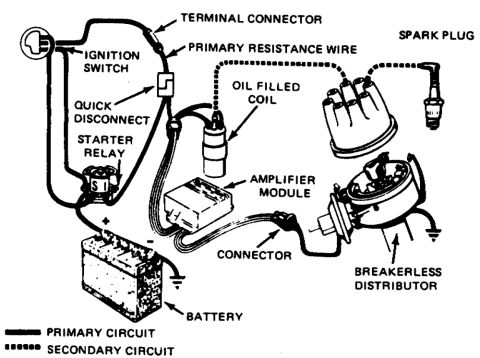












Ignition system wiring diagram showing primary and secondary circuits through coil, amplifier module, breakerless distributor and battery.
Part of 1987-1991 Ford Bronco Wiring Diagrams
This document is a pictorial wiring diagram of a Ford breakerless (Duraspark II-style) ignition system, showing the physical components and how the primary and secondary circuits interconnect. Components illustrated and labeled include the ignition switch, a terminal connector, the primary resistance wire, a quick disconnect, the starter relay, the battery (with positive terminal and chassis ground), the oil-filled ignition coil, the amplifier module (ignition control module), an in-line connector, the breakerless distributor (shown with cap removed and installed, with its own ground), and a spark plug. A legend at the bottom distinguishes line types: a heavy solid line indicates the primary circuit (battery, ignition switch, resistance wire, module, coil primary, distributor pickup) and a dotted line indicates the secondary circuit (coil tower to distributor cap to spark plug). A reader can learn the overall layout and routing of the ignition system: the primary feed passes from the ignition switch through the terminal connector and primary resistance wire (with a quick disconnect) to the coil and amplifier module, while high-voltage secondary current runs from the coil to the distributor cap and out to the spark plugs. No wire colors, part numbers, resistance values, or model years are given.
Is this accurate? Sign in to help verify it.
Frequently asked questions
- What components are shown in this Duraspark II ignition diagram?
- The diagram labels the ignition switch, terminal connector, primary resistance wire, quick disconnect, starter relay, battery, oil filled coil, amplifier module, connector, breakerless distributor, and spark plug.
- How are the primary and secondary ignition circuits distinguished in the diagram?
- A legend shows the primary circuit as a heavy solid line and the secondary circuit as a dotted line.
- Where does the primary resistance wire connect in this system?
- The primary resistance wire runs from the terminal connector near the ignition switch, through a quick disconnect, toward the oil filled coil and amplifier module.
- What carries the secondary (high voltage) circuit in this diagram?
- The dotted secondary circuit runs from the oil filled coil to the distributor cap and out to the spark plug.
- Does the module connect to the distributor?
- Yes, the amplifier module wiring passes through a labeled connector to the breakerless distributor, which is shown grounded.






No comments yet.