Home/
Registry/
Ford/
Bronco/
1987-1991/
“Eddie Bauer”/
Photo
supermotors.net/registry/media/1044935
Ford Bronco Headlight Switch Knob & Shaft Removal Diagram - Hooked Tool Method

Reference · 1987-1991 BroncoAll 95 service procedures


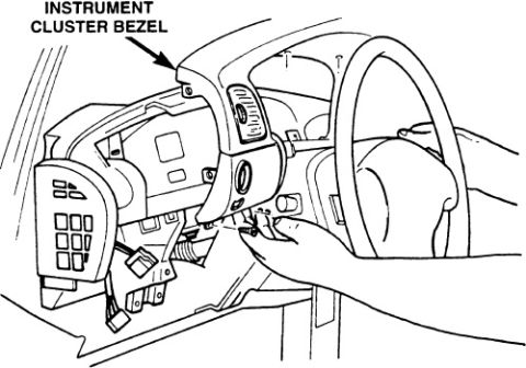
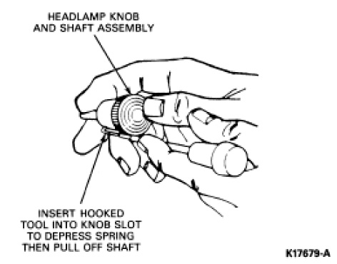












Service procedure illustration showing a hooked tool inserted into the headlamp knob slot to depress the spring and remove the shaft.
Part of 1987-1991 Ford Bronco Service Procedures
This document is a single service illustration showing how to remove the headlamp knob and shaft assembly from a headlight switch. The line drawing depicts a hand holding the headlamp switch knob and shaft, with two labeled callouts. The first callout identifies the 'HEADLAMP KNOB AND SHAFT ASSEMBLY.' The second callout instructs the technician to 'INSERT HOOKED TOOL INTO KNOB SLOT TO DEPRESS SPRING THEN PULL OFF SHAFT.' The figure is identified by the illustration reference number K17679-A in the lower right corner. From this document, a reader learns the removal technique for the headlamp switch knob/shaft: a hooked tool must be inserted into a slot on the knob to depress an internal retaining spring, after which the shaft can be pulled off (out of the switch). The document contains no year, model, torque, wiring, or part number information beyond the figure reference code; it is one page of a larger headlight switch service procedure set (uploaded alongside cluster trim panel and dash panel removal pages). It is applicable to Ford-style headlamp switches that use a spring-release knob and shaft, as commonly found in Ford trucks such as the claimed 1990 Bronco.
Is this accurate? Sign in to help verify it.
Frequently asked questions
- How do you remove the headlight switch knob and shaft on a Ford Bronco?
- Per the diagram, insert a hooked tool into the slot on the headlamp knob to depress the retaining spring, then pull off the knob and shaft assembly.
- What tool is needed to remove the headlamp knob and shaft assembly?
- A hooked tool that fits into the knob slot to depress the internal spring.
- What part is being removed in this illustration?
- The headlamp knob and shaft assembly, shown being held in the hand while the hooked tool releases it.
- What is the figure reference number for this illustration?
- K17679-A, printed in the lower right corner of the diagram.






No comments yet.