SuperMotors SuperMotors SUPERMOTORS Search: try “orange Bronco on 35s”
Home/ Registry/ Ford/ Bronco/ 1987-1991/ “Eddie Bauer”/ Photo supermotors.net/registry/media/1006305

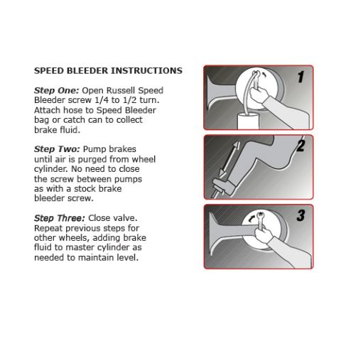
Russell Speed Bleeder three-step brake bleeding instructions wit…

Russell Speed Bleeder three-step brake bleeding instructions with illustrated steps
Russell Speed Bleeder three-step brake bleeding instructions with illustrated stepsOriginal file
Russell Speed Bleeder three-step brake bleeding instructions with illustrated steps

Reference · 1987-1991 BroncoAll 95 service procedures
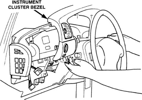
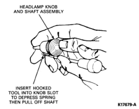
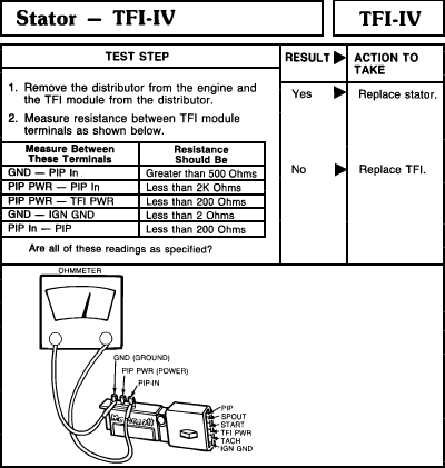
Ford Bronco Instrument Cluster Bezel Removal Diagram - Dash Trim Panel Ford Bronco Headlight Switch Knob & Shaft Removal Diagram - Hooked Tool Method Tuff Stuff Ford PMGR Starter Install Instructions 6124 6131 6132 - Wiring Russell Speed Bleeder three-step brake bleeding instructions with illustrated steps MSD Noise Filter Capacitor PN 8830 Install Diagram - MSD 6AL Ignition Wiring TFI-IV stator resistance test chart with ohmmeter and TFI module terminal illustration 1990 Ford Bronco Instrument Cluster Troubleshooting 60-9 - Voltmeter & Warning 1990 Ford Bronco Instrument Cluster Troubleshooting Hints (60-8) - Gauges & Tach 95service procedures1987-1991 Ford Bronco More reference 1973-1974 Ford Point-Type Ignition System Circuit Diagram - Coil & DistributorWiring diagram Ford Thermactor Air Bypass Valve Cutaway Diagram - Port IdentificationSchematic Ford 5.8L important engine information decal with 10° BTDC timing check and ASF-32C plugSpec plate Ford 5.0L V8 PCV Valve & Hose Routing Diagram - 9A474, 6B890, 6A664Exploded parts Ford 5.0L/5.8L Air Throttle Body Assembly Diagram - Canister Purge Ports & TPSManual page 1990 Bronco Major Standard Equipment sheet with interior features and functional specs by trimBrochure Borgeson Steering Intermediate Shaft Measurement Diagram - U-Joint Length B & CBlueprint Ford Thermactor Combination Valve Diagram - Air Bypass/Control Ports LabeledVacuum routing 1990 Ford Bronco Fuse Panel Diagram: Fuse Positions, Amps & Circuits (11-2)Fuse chart Ford V8 Intake Manifold Bolt Tightening Sequence Diagram - Stud LocationsTorque spec

Speed Bleeder steps: open the Russell Speed Bleeder screw 1/4 to 1/2 turn, pump brakes until air is purged, then close the valve and repeat at each wheel.

Part of 1987-1991 Ford Bronco Service Procedures

AI caption · Photo 1576 of 1787

5pm) (mm [usmucnous Step One: Oven Russen Speed Bleeder screw 1/4 [a 1/2 tum. Attach hnse to Slzeed Eleeder hag nrcalch can [a mllect brake uid. step Twa: Pump brakes until alr .s purged fmm wheel cylmder. No need to dose the screw between uumps as mm a stock brake hleeder screw. 5M0 Thm: Cose valve. Repeat urewous steps for other whees, adding make uld to master Cvllnder as needed to msmtam leveL

Is this accurate? Sign in to help verify it.

Comments

No comments yet.

More 1987-1991 Broncos