Home/
Registry/
Ford/
Bronco/
1987-1991/
“Eddie Bauer”/
Photo
supermotors.net/registry/media/1045016
Ford Bronco Instrument Cluster Bezel Removal Diagram - Dash Trim Panel

Reference · 1987-1991 BroncoAll 95 service procedures


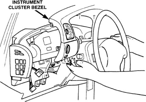












Service procedure illustration showing removal of the instrument cluster bezel from the dashboard.
Part of 1987-1991 Ford Bronco Service Procedures
This document is a single black-and-white service manual illustration depicting the removal (or installation) of an instrument cluster bezel from a vehicle dashboard. The only text in the image is the callout label "INSTRUMENT CLUSTER BEZEL" with an arrow pointing to the trim panel that surrounds the instrument cluster. The drawing shows a technician's hand grasping the bezel, which has been partially pulled away from the dash, exposing the instrument cluster opening, wiring/connectors behind the panel, the steering wheel, and the steering column area. A switch pod (appearing to contain buttons/switches) is shown attached to or hanging from the left side of the bezel. The illustration was uploaded to accompany a claimed 1990 Ford Bronco, filed as "Cluster Trim Panel.jpg," and appears to be part of a multi-page set that also includes dash panel removal and headlight switch pages. A reader can learn the general location and orientation of the instrument cluster bezel and see that it is removed by pulling it away from the dash over the steering column, but the document contains no written procedure steps, fastener locations, torque specifications, or part numbers.
Is this accurate? Sign in to help verify it.
Frequently asked questions
- What part is shown being removed in this diagram?
- The diagram labels and shows the removal of the instrument cluster bezel, the trim panel surrounding the instrument cluster above the steering column.
- Where is the instrument cluster bezel located?
- Per the illustration, it is the panel directly in front of the driver, surrounding the gauge cluster and fitting around/above the steering column.
- Does this document list any torque specs, fasteners, or part numbers?
- No. The only text in the document is the callout label "INSTRUMENT CLUSTER BEZEL"; no written steps, fasteners, torque values, or part numbers appear.
- How is the bezel shown being removed?
- The illustration shows a hand pulling the bezel outward and away from the dashboard, tilting it over the steering column, with attached switches and wiring still connected behind it.






No comments yet.