Home/
Registry/
Ford/
Bronco/
1987-1991/
“Eddie Bauer”/
Photo
supermotors.net/registry/media/1046697
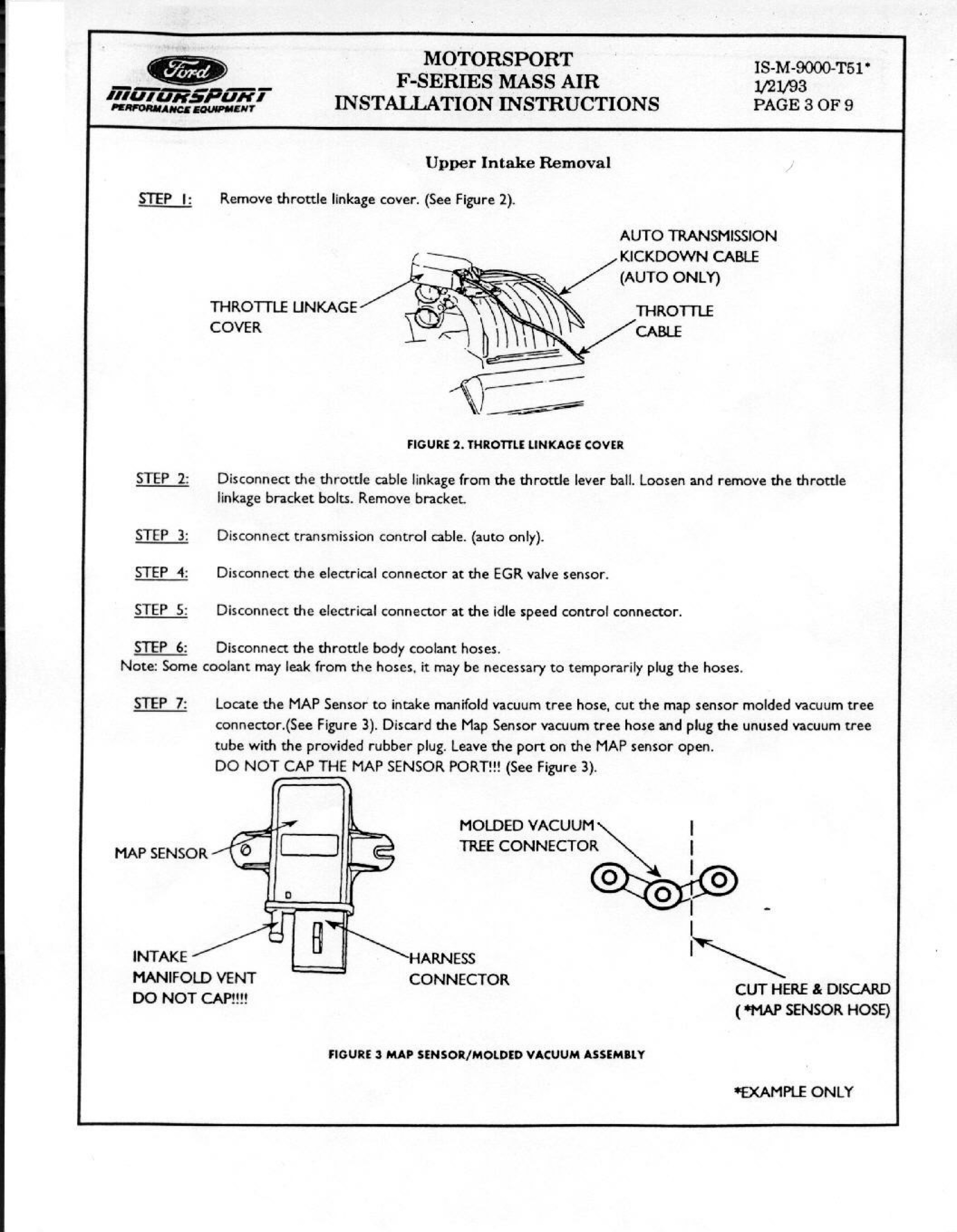
Ford Motorsport F-Series Mass Air Install Instructions Pg 3 - Upper Intake Removal
Reference · 1987-1991 BroncoAll 95 service procedures
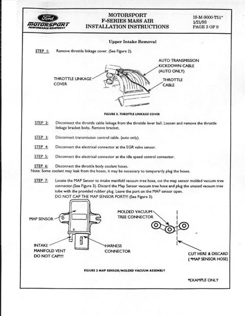












Page 3 of the Ford Motorsport Mass Air install: upper intake removal steps, disconnecting throttle/kickdown cables, EGR and IAC connectors, and cutting/plugging the MAP sensor molded vacuum tree hose.
Part of 1987-1991 Ford Bronco Service Procedures
This document is page 3 of 9 of the Ford Motorsport (Performance Equipment) F-Series Mass Air installation instructions, document number IS-M-9000-T51, dated 1/21/93. This page covers the 'Upper Intake Removal' portion of the mass air conversion procedure in seven steps: removing the throttle linkage cover (illustrated in Figure 2, which labels the throttle linkage cover, throttle cable, and automatic transmission kickdown cable), disconnecting the throttle cable linkage from the throttle lever ball and removing the linkage bracket, disconnecting the transmission control cable (automatic transmissions only), disconnecting the electrical connectors at the EGR valve sensor and idle speed control, disconnecting the throttle body coolant hoses (with a note that coolant may leak and hoses may need temporary plugging), and modifying the MAP sensor vacuum connection. Step 7 instructs the installer to cut the MAP sensor molded vacuum tree connector, discard the MAP sensor vacuum tree hose, plug the unused vacuum tree tube with the provided rubber plug, and leave the MAP sensor port open, emphasizing 'DO NOT CAP THE MAP SENSOR PORT!!!'. Figure 3 illustrates the MAP sensor/molded vacuum assembly, labeling the MAP sensor, harness connector, intake manifold vent, and where to cut and discard the hose.
Is this accurate? Sign in to help verify it.
Frequently asked questions
- What does Step 7 of the Ford Motorsport Mass Air installation say to do with the MAP sensor vacuum hose?
- Cut the MAP sensor molded vacuum tree connector, discard the MAP sensor vacuum tree hose, plug the unused vacuum tree tube with the provided rubber plug, and leave the port on the MAP sensor open. The document warns: DO NOT CAP THE MAP SENSOR PORT!!!
- Which electrical connectors are disconnected during upper intake removal?
- The electrical connector at the EGR valve sensor (Step 4) and the connector at the idle speed control (Step 5).
- Do I need to disconnect the transmission control cable?
- Yes, but only on automatic transmission vehicles, Step 3 says to disconnect the transmission control cable (auto only).
- What should I expect when disconnecting the throttle body coolant hoses?
- The document notes some coolant may leak from the hoses and it may be necessary to temporarily plug them.
- What is the document number and date of this instruction sheet?
- IS-M-9000-T51, dated 1/21/93, page 3 of 9 of the Ford Motorsport F-Series Mass Air Installation Instructions.






No comments yet.