Home/
Registry/
Ford/
Bronco/
1987-1991/
“Eddie Bauer”/
Photo
supermotors.net/registry/media/1069662
1990 Ford Bronco Speed Control Wiring Diagram 31-1 - Cruise Control Circuit
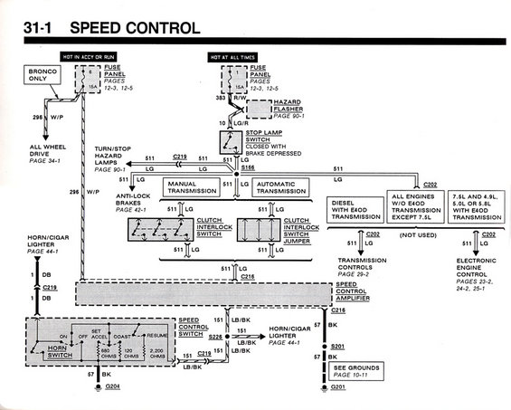
Speed control wiring diagram (page 31-1) showing the speed control amplifier, switches, fuse panel, and color-coded circuits with connector callouts.
This is page 31-1 of a Ford wiring diagram covering the Speed Control (cruise control) circuit, uploaded as applying to a 1990 Ford Bronco. The diagram traces power from two fuse panel sources: Fuse 6 (15A, hot in accessory or run, marked "Bronco Only") supplying circuit 296 W/P, and Fuse 1 (15A, hot at all times) supplying circuit 383 R/W through the hazard flasher and circuit 10 LG/R to the stop lamp switch (closed with brake depressed). Circuit 511 LG branches from splice S166 to the turn/stop hazard lamps, anti-lock brakes, the clutch interlock switch (manual transmission) or clutch interlock switch jumper (automatic transmission), and via connector C202 to transmission controls (diesel with E4OD) or electronic engine control (7.5L and 4.9L/5.0L/5.8L with E4OD). The 511 LG circuit reaches the speed control amplifier at C216. The speed control switch (ON, OFF, SET ACCEL, COAST, RESUME with 680, 120, and 2,200 ohm resistors) and horn switch route circuit 151 LB/BK through S226 and C219 to the horn/cigar lighter circuit (page 44-1), with grounds at G204 and G201 via circuit 57 BK and splice S201. Cross-references to related pages (10-11, 12-3, 12-5, 23-2, 24-2, 25-1, 29-2, 34-1, 42-1, 44-1, 90-1) are included.
Is this accurate? Sign in to help verify it.
Frequently asked questions
- Which fuses power the speed control circuit on this diagram?
- Two fuse panel fuses: Fuse 6, 15A (hot in accessory or run, marked "Bronco Only") on circuit 296 W/P, and Fuse 1, 15A (hot at all times) on circuit 383 R/W. Fuse panel details are on pages 12-3 and 12-5.
- What wire color is circuit 511 in the speed control system?
- Circuit 511 is LG (light green). It runs from the stop lamp switch through splice S166 to the turn/stop hazard lamps, anti-lock brakes, clutch interlock switch or jumper, and to the speed control amplifier at connector C216.
- What is the difference between manual and automatic transmissions in this circuit?
- Manual transmission vehicles use a clutch interlock switch, while automatic transmission vehicles use a clutch interlock switch jumper, both carrying circuit 511 LG.
- What resistance values are inside the speed control switch?
- The switch shows 680 ohms, 120 ohms, and 2,200 ohms resistors associated with the SET ACCEL, COAST, and RESUME functions, with ON and OFF positions also shown.
- When does the stop lamp switch close?
- The stop lamp switch is closed with the brake depressed; it is fed by circuit 10 LG/R from the hazard flasher and outputs circuit 511 LG.
Comments
More from this build














No comments yet.