Home/
Registry/
Ford/
Bronco/
1978-1979/
1978 Ford Bronco/
Photo
supermotors.net/registry/media/1089405
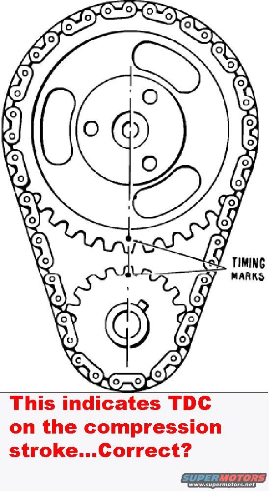
Ford Timing Chain Sprocket Alignment Diagram - Cam & Crank Timing Marks
Reference · 1978-1979 BroncoAll 48 service procedures

Service figure showing timing chain and sprocket marks aligned to indicate TDC on the compression stroke.
Part of 1978-1979 Ford Bronco Service Procedures
This document is a line-art illustration of a timing chain and sprocket assembly, showing the large camshaft sprocket at the top and the smaller crankshaft sprocket at the bottom, connected by a timing chain. A dashed vertical centerline passes through both sprocket centers, and a callout labeled 'TIMING MARKS' points to two dots, one on the camshaft sprocket and one on the crankshaft sprocket, positioned adjacent to each other along the centerline between the two sprockets (cam mark at the bottom of the cam sprocket, crank mark at the top of the crank sprocket). A red text annotation added by the uploader asks: 'This indicates TDC on the compression stroke...Correct?' The diagram itself contains no year, make, model, engine, torque, or part-number information; it purely illustrates the correct alignment of the camshaft and crankshaft sprocket timing marks when installing or checking a timing chain. It was uploaded to a 1978 Ford Bronco gallery alongside a Ford 351C/351M related document, suggesting it pertains to Ford V8 timing set alignment, though the document itself does not state applicability.
Is this accurate? Sign in to help verify it.
Frequently asked questions
- Where are the timing marks located on the sprockets in this diagram?
- The 'TIMING MARKS' callout points to a dot on the bottom edge of the camshaft (upper) sprocket and a dot on the top edge of the crankshaft (lower) sprocket, aligned with each other along the vertical centerline between the two sprockets.
- How should the camshaft and crankshaft sprockets be aligned according to this diagram?
- The two timing mark dots should face each other, both lying on the straight line drawn through the centers of the camshaft and crankshaft sprockets.
- What question does the uploader's annotation ask?
- The red annotation asks: 'This indicates TDC on the compression stroke...Correct?', the diagram itself does not answer this question.
- Does this document give any torque specs or part numbers?
- No. It is only an illustration of timing mark alignment with a single 'TIMING MARKS' callout; no torque values, part numbers, or other specifications appear.
No comments yet.