Home/
Registry/
Ford/
Bronco/
1987-1991/
“Street Truck”/
Photo
supermotors.net/registry/media/1090704
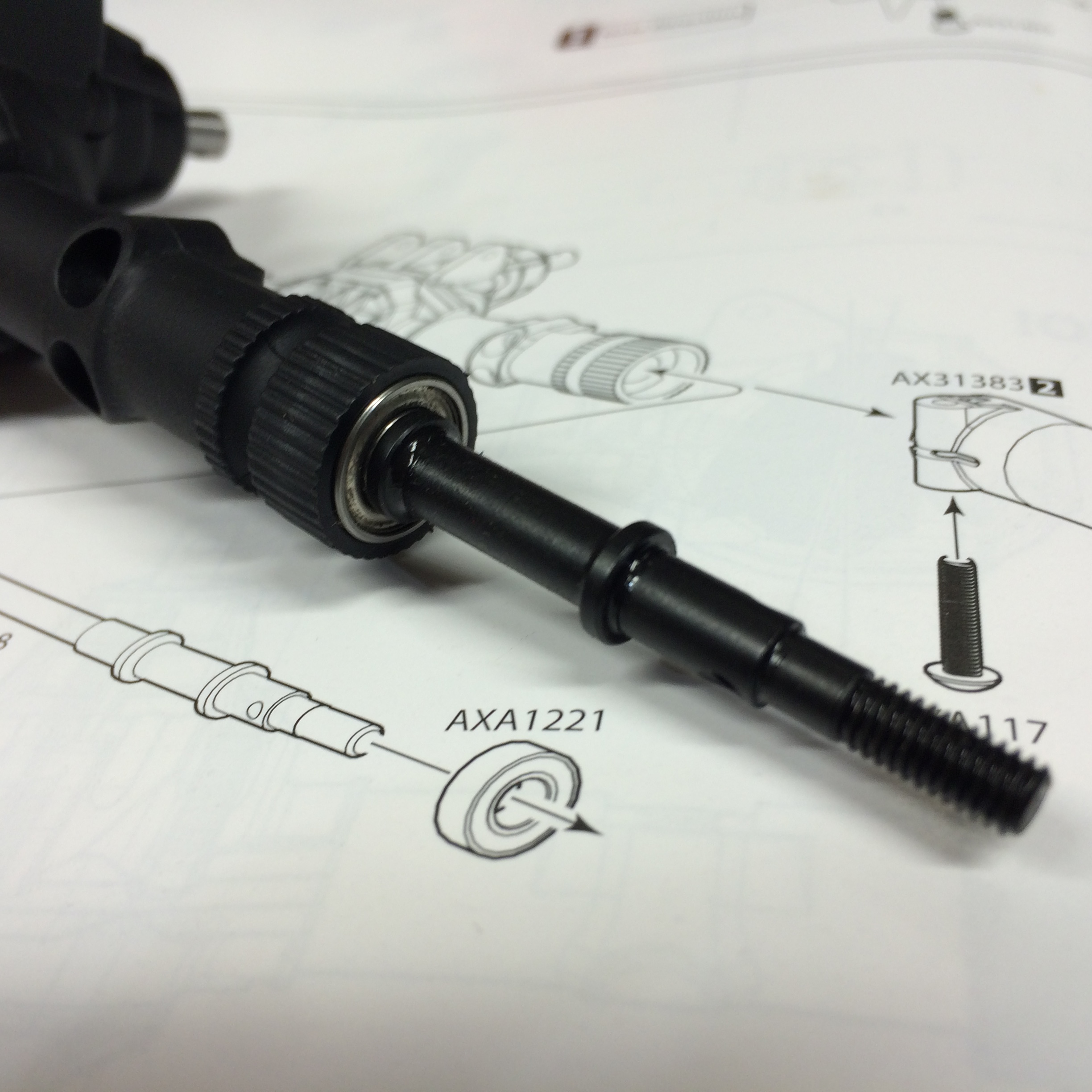
Axial RC Axle/Transmission Exploded Assembly Diagram - AX31383, AXA1221 Parts
Reference · 1987-1991 BroncoAll 64 exploded parts diagrams



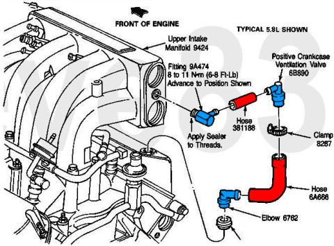
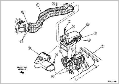
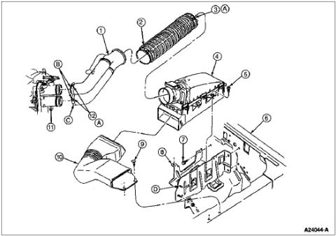
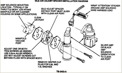
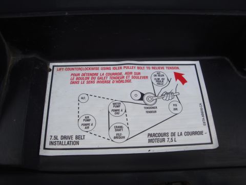








Exploded parts breakdown drawing of a steering/shaft assembly with part numbers AXA1221 and AX31383, overlaid with the physical part.
Part of 1987-1991 Ford Bronco Exploded Parts Diagrams
This image shows a page from an assembly instruction manual (exploded-parts style line drawings) with an actual assembled component photographed lying on top of it. The printed diagram illustrates the assembly of a shaft/bearing/motor-mount area: a bearing labeled AXA1221 slides onto a stepped shaft, a button-head machine screw is shown installing into a component labeled AX31383 (with a quantity badge of 2), and a third partially visible callout ends in "A117." The physical part on the paper is a black plastic housing with a knurled collar, a visible ball bearing, and a black steel stub shaft with a machined step, groove, and threaded end, apparently the real-world counterpart of the shaft shown in the drawing. The part numbers use Axial Racing's AX/AXA prefix convention, indicating this is an instruction sheet for an Axial RC vehicle kit (such as an axle or transmission assembly step), not a full-size automotive document. No year, vehicle model, torque specs, fuse data, or wiring information is visible. A reader can learn which Axial part numbers (AX31383, AXA1221) are used at this assembly step and the orientation in which the bearing and screw install.
Is this accurate? Sign in to help verify it.
Frequently asked questions
- What part numbers are visible in this exploded diagram?
- AX31383 (with a quantity indicator of 2), AXA1221 (shown as a bearing), and a partially visible number ending in 'A117'.
- What is part AXA1221 in this diagram?
- It is drawn as a bearing that slides onto a stepped shaft, shown with an arrow indicating installation direction.
- How does the screw install relative to AX31383?
- A button-head screw is shown with an upward arrow installing into the underside of the component labeled AX31383.
- Is this a document for a full-size vehicle?
- No vehicle year or model is shown; the page is an exploded assembly instruction sheet using AX/AXA-prefixed part numbers, with a small physical part assembly photographed on top of it.





No comments yet.