Home/
Registry/
Ford/
Bronco/
1987-1991/
“Eddie Bauer”/
Photo
supermotors.net/registry/media/1050472
Ford IABP Idle Air Adjust Spacer Installation Diagram (TB-2433-A) 5.8L 7.5L

Reference · 1987-1991 BroncoAll 61 exploded parts diagrams
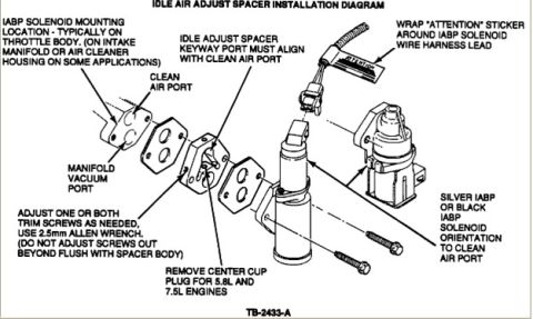












Exploded installation diagram of the idle air adjust spacer with gaskets, IABP solenoid, trim screws and alignment notes.
Part of 1987-1991 Ford Bronco Exploded Parts Diagrams
This document is an exploded parts installation diagram titled "Idle Air Adjust Spacer Installation Diagram" (drawing reference TB-2433-A). It illustrates how an idle adjust spacer is installed between gaskets and the IABP (Idle Air Bypass) solenoid, along with mounting bolts. Key instructions in the callouts include: the IABP solenoid is typically mounted on the throttle body (or on the intake manifold or air cleaner housing on some applications); the idle adjust spacer keyway port must align with the clean air port; the clean air port and manifold vacuum port on the mounting flange are identified; one or both trim screws on the spacer may be adjusted as needed using a 2.5mm Allen wrench, but the screws must not be adjusted out beyond flush with the spacer body; the center cup plug must be removed for 5.8L and 7.5L engines; the silver or black IABP solenoid must be oriented to the clean air port; and an "ATTENTION" sticker should be wrapped around the IABP solenoid wire harness lead. This diagram helps a reader correctly orient and install the idle air adjust spacer and IABP solenoid and adjust idle trim screws.
Is this accurate? Sign in to help verify it.
Frequently asked questions
- Where is the IABP solenoid typically mounted?
- Typically on the throttle body; on some applications it is mounted on the intake manifold or air cleaner housing.
- What tool is used to adjust the trim screws on the idle adjust spacer?
- A 2.5mm Allen wrench. Adjust one or both trim screws as needed, but do not adjust the screws out beyond flush with the spacer body.
- How must the idle adjust spacer be oriented during installation?
- The spacer's keyway port must align with the clean air port, and the silver or black IABP solenoid must be oriented to the clean air port.
- When should the center cup plug be removed?
- The center cup plug must be removed for 5.8L and 7.5L engines.
- What should be done with the IABP solenoid wire harness lead?
- Wrap an "ATTENTION" sticker around the IABP solenoid wire harness lead.






No comments yet.