Home/
Registry/
Ford/
Bronco/
1987-1991/
“Eddie Bauer”/
Photo
supermotors.net/registry/media/1098261
Ford 5.8L EFI PCV Valve & Hose Routing Diagram - Part Numbers & Torque Specs

Reference · 1987-1991 BroncoAll 61 exploded parts diagrams

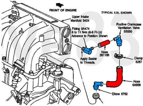











Parts diagram of a typical 5.8L PCV system showing the PCV valve, hoses, clamp, elbow, and intake manifold fitting with part numbers and torque.
Part of 1987-1991 Ford Bronco Exploded Parts Diagrams
This document is an exploded parts diagram of the Positive Crankcase Ventilation (PCV) hose assembly on a Ford 5.8L EFI engine, labeled "TYPICAL 5.8L SHOWN." The illustration shows the upper intake manifold (part 9424) with an arrow indicating the front of the engine. Components of the PCV system are shown exploded off the manifold: a fitting (9A474) that threads into the upper intake manifold with a torque spec of 8 to 11 N·m (6-8 ft-lb), with instructions to apply sealer to the threads and advance the fitting to the position shown; a hose (381188) connecting the fitting to the PCV valve (6B890); a clamp (8287); a second hose (6A666); and an elbow (6762) that leads down toward the valve cover grommet. The diagram gives readers the Ford base part numbers for each PCV plumbing component, the routing/orientation of the hoses, and the installation torque and sealing requirements for the manifold fitting. It is useful for anyone servicing or replacing PCV hoses, the PCV valve, or the intake manifold fitting on a 5.8L (351W) EFI engine such as those found in full-size Ford trucks and Broncos.
Is this accurate? Sign in to help verify it.
Frequently asked questions
- What is the torque spec for the PCV fitting on the 5.8L upper intake manifold?
- The fitting (9A474) is torqued to 8 to 11 N·m (6-8 ft-lb), then advanced to the position shown. Sealer should be applied to the threads.
- What is the Ford part number for the PCV valve on the 5.8L engine?
- The Positive Crankcase Ventilation Valve is base part number 6B890.
- What are the part numbers for the PCV hoses and connectors?
- Hose 381188 connects the fitting to the PCV valve; hose 6A666 with clamp 8287 connects the PCV valve to elbow 6762.
- Where does the PCV system connect on the intake?
- It connects to the Upper Intake Manifold (9424) via fitting 9A474, which must have sealer applied to its threads.
- Which engine does this diagram cover?
- The diagram is labeled 'TYPICAL 5.8L SHOWN', covering the 5.8L engine's PCV hose arrangement.






No comments yet.