Home/
Registry/
Ford/
Bronco/
1987-1991/
“Eddie Bauer”/
Photo
supermotors.net/registry/media/1068884
1990 Ford Bronco Air Intake Tube & Air Cleaner MAF - Exploded Parts Diagram

Reference · 1987-1991 BroncoAll 61 exploded parts diagrams

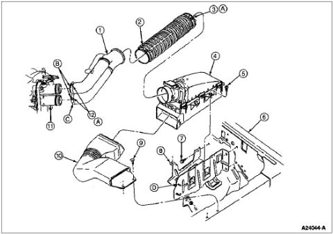











Exploded parts diagram of an air intake system showing the duct, air cleaner housing, and resonator with numbered and lettered component callouts.
Part of 1987-1991 Ford Bronco Exploded Parts Diagrams
This document is a scanned exploded-view illustration of an air intake tube and air cleaner assembly, apparently for a Ford truck with a mass air flow (MAF) style intake system based on the uploader's filename. The line drawing shows a corrugated flexible air intake hose/tube (callout 2), a rigid outlet tube connecting to the engine throttle body (callout 1), an air cleaner housing assembly (callout 4) with its cover and element area, mounting brackets and fasteners on the fender apron/inner body panel (callouts 5-9), an air inlet duct/snorkel (callout 10), and connections at the engine (callouts 11, 12). Numbered callouts 1 through 12 and letter callouts A, B, C, and D identify components and fastener/attachment points, but no accompanying legend, parts list, part numbers, or torque specifications are included on this page, those would presumably appear on a companion page. The Ford illustration reference number A24044-A appears in the lower right corner. A reader can learn the physical arrangement, routing, and mounting locations of the air intake tube and air cleaner components, though specific part names and numbers are not identified on this page.
Is this accurate? Sign in to help verify it.
Frequently asked questions
- What does this diagram show?
- It is an exploded-view illustration of an air intake tube and air cleaner assembly, showing a flexible corrugated intake hose, air cleaner housing, inlet duct, mounting brackets, and their attachment points on the engine and body panel.
- How many parts are called out in the diagram?
- There are twelve numbered callouts (1 through 12) plus letter callouts A, B, C, and D marking components and attachment points.
- Does the diagram include a parts list or part numbers?
- No. This page contains only the illustration with numbered/lettered callouts. No legend, part names, part numbers, or torque values are printed on the page. The only identifying text is the drawing number A24044-A.
- What is the Ford illustration reference number for this diagram?
- The drawing is identified as A24044-A in the lower right corner.






No comments yet.