Home/
Registry/
Ford/
Bronco/
1992-1996/
1996 Ford Bronco/
Photo
supermotors.net/registry/media/1090772
1994 Ford Bronco/F-Series EVTM Grounds 10-10 - Module Ground Wiring Diagram

Reference · 1992-1996 BroncoAll 411 wiring diagrams
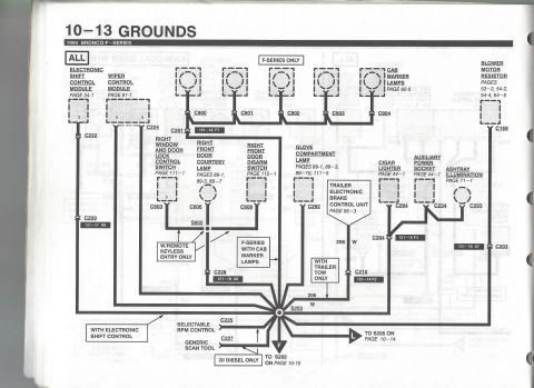
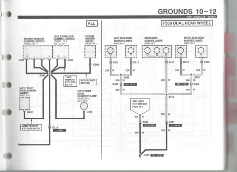
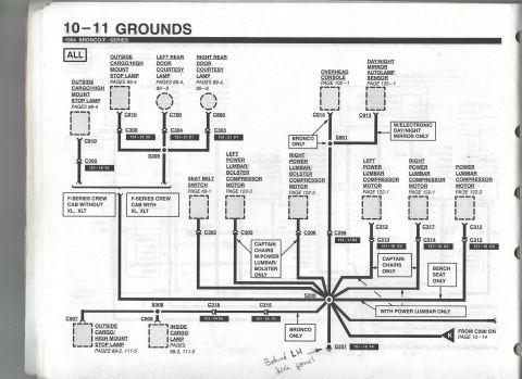
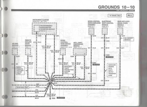
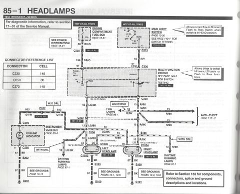

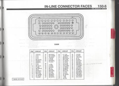
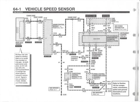
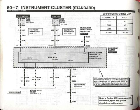
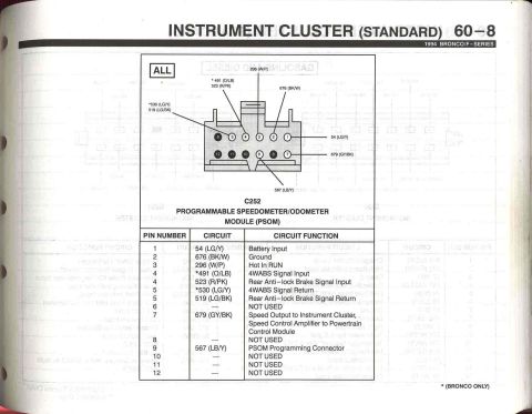
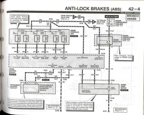
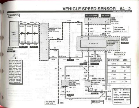




Ford 1994 Bronco/F-Series ground distribution wiring diagram showing instrument cluster, RABS, speed-control and anti-theft modules with color-coded circuits.
Part of 1992-1996 Ford Bronco Wiring Diagrams
This is page 10-10, "Grounds," from the 1994 Ford Bronco/F-Series Electrical and Vacuum Troubleshooting Manual (EVTM). The diagram shows ground circuit wiring for multiple electronic modules, all converging at splice S216 and terminating at ground point G200 (component view reference 151-20 A3). Modules shown include the Instrument Cluster (pages 60-1, 60-7, 64-1), Programmable Speedometer/Odometer Module (page 64-1, connectors C252/C251), Air Bag Module (page 46-1, C218), Remote Keyless Entry Module (page 111-1, C241), Speed Control/Horn Switch Assembly (pages 31-1, 31-3, C219), Anti-Theft Controller Module (page 112-2, C238), Speed Control Servo/Amplifier Assembly (page 31-4, C216), Electronic Shift Control Module (page 34-1, C222/C209), and the Rear Anti-Lock Brake (RABS) Module (page 42-1, C277, noted "ALL EXCEPT BRONCO"). Ground wire circuits include 570 BK/W, 875 BK/LB (DI diesel only, per asterisk note), 676 PK/O, 629 BR, 901 R/LB, and 530 LG/Y. Applicability callouts specify options like remote keyless entry, anti-theft protection, air bag, and gasoline engine with shift-on-fly transfer case. Connector view references C202 (151-2 A7) and C209 (151-17 A8) are given.
Is this accurate? Sign in to help verify it.
Frequently asked questions
- What ground point do the instrument cluster, RABS module, and speed control modules use on a 1994 Bronco/F-Series?
- They all route through splice S216 to ground G200 (component location reference 151-20 A3).
- What wire color is circuit 570 on this ground diagram?
- Circuit 570 is BK/W (black with white stripe).
- What does the asterisk (*) next to circuit 875 mean?
- The legend states "* DI DIESEL ONLY," so circuit 875 BK/LB applies only to DI diesel vehicles.
- Does the Rear Anti-Lock Brake (RABS) module ground apply to the Bronco?
- No: the RABS module (page 42-1, connector C277, circuit 530 LG/Y) is labeled "ALL EXCEPT BRONCO."
- What circuit grounds the air bag module?
- The Air Bag Module (page 46-1, connector C218, pin 7) grounds through circuit 629 BR, shown "W/AIR BAG ONLY."






No comments yet.