Home/
Registry/
Ford/
Bronco/
1992-1996/
1996 Ford Bronco/
Photo
supermotors.net/registry/media/1090773
1994 Ford Bronco/F-Series EVTM Grounds Diagram Pg 10-11 - G201 S200 Wiring

Reference · 1992-1996 BroncoAll 411 wiring diagrams
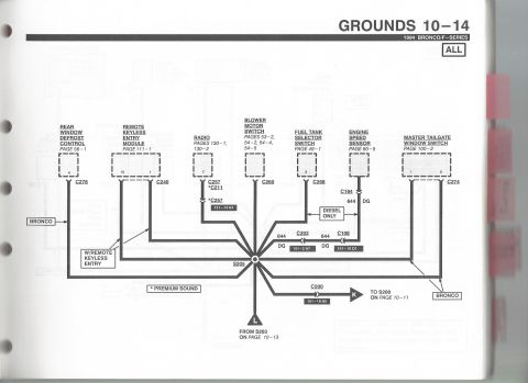
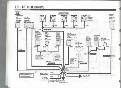
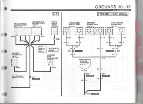
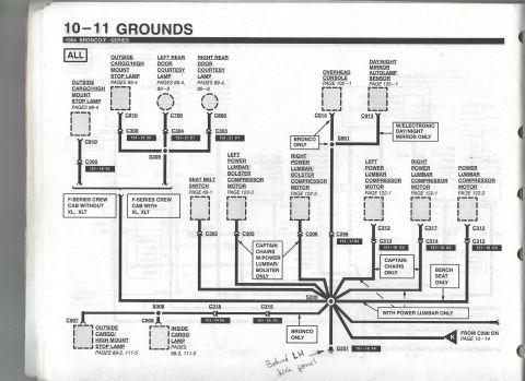
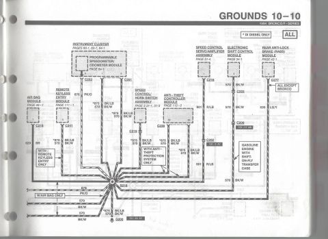
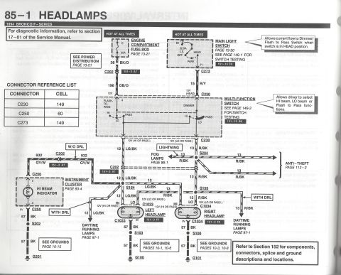

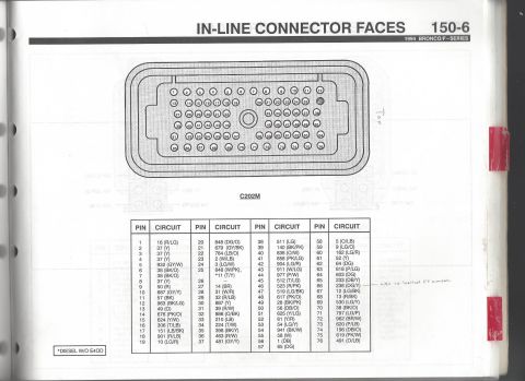
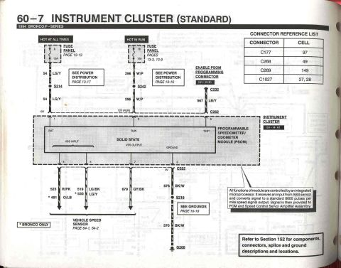




Ford ground wiring diagram for courtesy lamps, power lumbar compressor motors and seat belt switch with splice points.
Part of 1992-1996 Ford Bronco Wiring Diagrams
This is page 10-11 ("Grounds") from the 1994 Ford Bronco/F-Series Electrical and Vacuum Troubleshooting Manual (EVTM). The diagram, applicable to ALL models, maps interior ground circuit distribution centered on splice S200 and ground point G201 (component view 151-18 F4), which a handwritten note locates "Behind LH kick panel." Grounded components shown include the outside cargo/high mount stop lamps (C910/C300), left and right rear door courtesy lamps (C700/C304 and C800/C303, F-Series crew cab variants with and without XL/XLT trim), overhead console (C914, Bronco only), day/night mirror autolamp sensor (C913/S901, with electronic day/night mirror only), seat belt switch (C302), left and right power lumbar/bolster compressor motors (C305/C306, captain chairs with power lumbar/bolster only), left and right power lumbar compressor motors (C312/C313, C317/C314, captain chairs only), power lumbar compressor motor for bench seat (C312/C313), inside cargo lamp (S308/C908), and connectors C318, C315, C299. Each component references its schematic page (e.g., 89-4, 102-1, 122-1 through 122-3, 125-1) and connector location grid references (e.g., 151-19 B1). The circuit continues from C200 on page 10-14. Useful for tracing ground faults affecting interior lamps, seat compressors, and console accessories.
Is this accurate? Sign in to help verify it.
Frequently asked questions
- Where is ground G201 located on a 1994 Bronco/F-Series?
- The diagram references G201's component view at 151-18 F4, and a handwritten note on this scan indicates it is located behind the LH (left-hand) kick panel.
- What components ground through splice S200 on this diagram?
- S200 collects grounds from the overhead console (C914, Bronco only), day/night mirror autolamp sensor (C913), seat belt switch (C302), power lumbar/bolster compressor motors (C305, C306, C312, C317), cargo lamps, and rear door courtesy lamps, feeding to ground G201.
- Which grounds are Bronco-only on this page?
- The overhead console circuit through C914 and the branch feeding ground G201 are both labeled 'BRONCO ONLY.'
- What connectors serve the power lumbar compressor motors?
- Left power lumbar compressor motor uses C312 to C313 (151-16 C9), right uses C317 to C314 (151-16 A3), captain chairs only; the bench-seat power lumbar compressor motor uses C312 to C313 (151-16 C9).
- What page do the rear door courtesy lamp circuits appear on?
- The left and right rear door courtesy lamps are referenced to pages 89-4 and 89-8, connecting through C700/C304 (151-21 E1) and C800/C303 (151-21 F7).






No comments yet.