Home/
Registry/
Ford/
Bronco/
1992-1996/
1996 Ford Bronco/
Photo
supermotors.net/registry/media/1090779
1994 Ford Bronco/F-Series EVTM Pg 10-9 Grounds - Radio, PCM & Air Bag G200
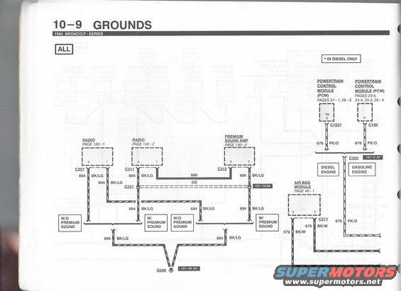
Ford ground wiring diagram for radio, premium sound amp, air bag module and powertrain control module grounds at G200.
Part of 1992-1996 Ford Bronco Wiring Diagrams
This is page 10-9 of the 1994 Ford Bronco/F-Series Electrical & Vacuum Troubleshooting Manual (EVTM), covering the Grounds section and marked 'ALL' (applies to all models, with a footnote '* DI Diesel Only' for one PCM pin). The wiring diagram shows how audio-system grounds route to ground point G200: the Radio (connectors C257 and C211), the Premium Sound Amp (connector C212), and the interconnecting circuit 689 (DB, dark blue) between radio pin 1 and amp pin 2. Ground circuits 694 (BK/LG, black/light green) run from these components through variants labeled 'W/ Premium Sound' and 'W/O Premium Sound' before terminating at G200 (component view reference 151-20 A3). The right side of the diagram shows Powertrain Control Module ground circuit 676 (PK/O, pink/orange) at connector C1027 pin 33/6 for the diesel engine and connector C185 pin 6 for the gasoline engine, joining at connector C202 (151-2 A7). The Air Bag Module (page 46-1) grounds via circuit 570 (BK/W) at connector C217 pins 3 and 5. Page cross-references to the radio (130-1, 130-2), premium sound amp (130-2), PCM (23-5 through 28-3), and air bag module (46-1) schematics are included.
Is this accurate? Sign in to help verify it.
Frequently asked questions
- What ground circuit does the radio use on a 1994 Bronco/F-Series?
- The radio grounds through circuit 694, a BK/LG (black/light green) wire, at connector C257 (pins 3 and 1) or C211 (pin 3), routing to ground point G200 (component view 151-20 A3).
- What is the PCM ground circuit and wire color on the 1994 Bronco/F-Series?
- The Powertrain Control Module grounds through circuit 676, a PK/O (pink/orange) wire, at connector C1027 (pin 33, DI diesel only / pin 6) for the diesel engine and connector C185 (pin 6) for the gasoline engine, joining at connector C202 (151-2 A7).
- How does the air bag module ground on the 1994 Bronco/F-Series?
- The Air Bag Module (schematic page 46-1) grounds through circuit 570, BK/W (black/white) wires, at connector C217 pins 3 and 5.
- What connects the radio to the premium sound amp in this diagram?
- Circuit 689, a DB (dark blue) wire, runs from radio connector C211 pin 1 to premium sound amp connector C212 pin 2.
- Where is ground G200 documented in the component views?
- G200 is referenced to component view page 151-20, grid A3.
Comments
More from this build












No comments yet.