Home/
Registry/
Ford/
Bronco/
1992-1996/
1996 Ford Bronco/
Photo
supermotors.net/registry/media/1090778
1994 Ford Bronco EVTM Grounds 10-16: 4WABS & Speedometer Ground Wiring Diagram

Reference · 1992-1996 BroncoAll 411 wiring diagrams
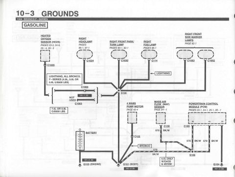
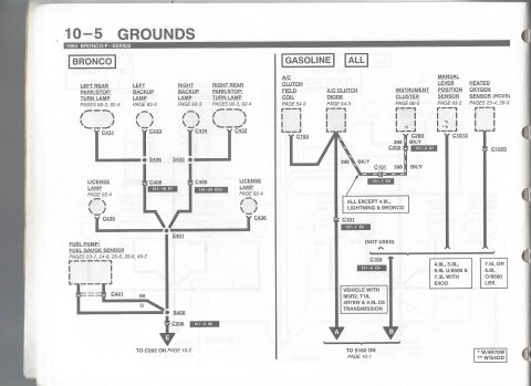
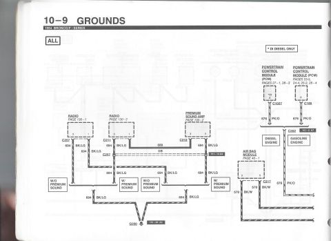
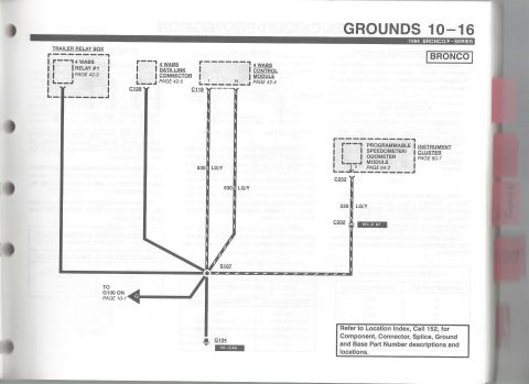
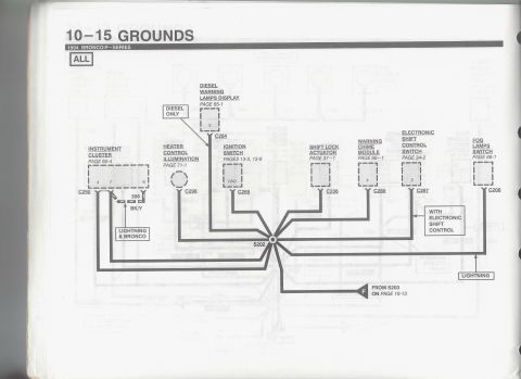
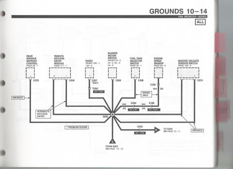
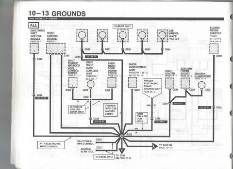
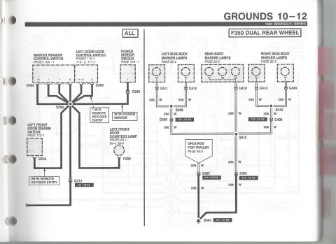
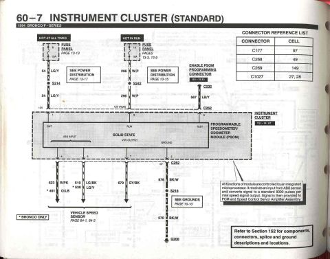
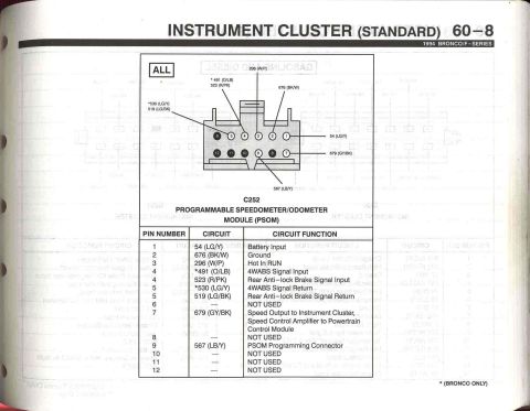
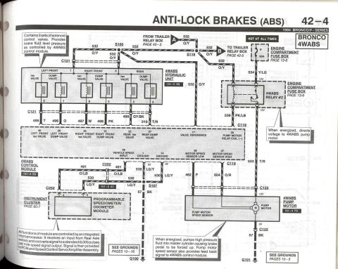
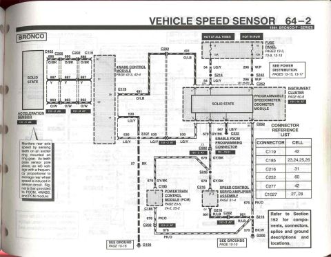




Ford Bronco ground wiring diagram showing 4WABS relay box, data link connector and speedometer module circuits to G104.
Part of 1992-1996 Ford Bronco Wiring Diagrams
This is page 10-16 ("Grounds") from the 1994 Ford Bronco/F-Series Electrical and Vacuum Troubleshooting Manual (EVTM), covering the Bronco. The wiring diagram shows the ground distribution for the 4-wheel anti-lock brake system (4WABS) and instrument cluster circuits. Circuit 530 (light green with yellow stripe, LG/Y) wires run from the 4WABS Relay #1 in the Trailer Relay Box (page 42-3), the 4WABS Data Link Connector at C120 (page 42-5), the 4WABS Control Module at connector C119 pins 1 and 14 (page 42-4), and the Programmable Speedometer/Odometer Module at pin 5 of the Instrument Cluster via connectors C252 and C202 (151-2 A7; pages 60-7 and 64-2). All of these grounds join at splice S107, which connects both to ground G104 (151-3 A9) and onward to ground G100 shown on page 10-1. A note directs readers to the Location Index, Cell 152, for component, connector, splice, ground, and base part number descriptions and locations. This page is useful for diagnosing ABS or speedometer ground faults on a 1994 Bronco.
Is this accurate? Sign in to help verify it.
Frequently asked questions
- What ground does the 4WABS control module use on a 1994 Ford Bronco?
- Pins 1 and 14 of the 4WABS Control Module (connector C119) ground through circuit 530 LG/Y wires to splice S107, which connects to ground G104 and also to G100 (shown on page 10-1).
- What wire color is the ground circuit for the ABS and speedometer on this diagram?
- Circuit 530, a light green wire with yellow stripe (LG/Y), is used for all the ground runs shown.
- How does the programmable speedometer/odometer module ground?
- Pin 5 of the Programmable Speedometer/Odometer Module in the instrument cluster grounds through connector C252, then C202 (151-2 A7), via a 530 LG/Y wire to splice S107 and ground G104.
- Where is 4WABS Relay #1 located according to this page?
- 4WABS Relay #1 is located in the Trailer Relay Box; its detailed circuit is on page 42-3.
- Where can I find connector and ground location details referenced on this diagram?
- The page directs you to the Location Index, Cell 152, for component, connector, splice, ground, and base part number descriptions and locations.






No comments yet.