SuperMotors SuperMotors SUPERMOTORS Search: try “orange Bronco on 35s”
Home/ Registry/ Ford/ Bronco/ 1992-1996/ “Buckin Bronco”/ Photo supermotors.net/registry/media/1122371

Ford 5.0L wiring diagram of the eight fuel injector circuits fee…
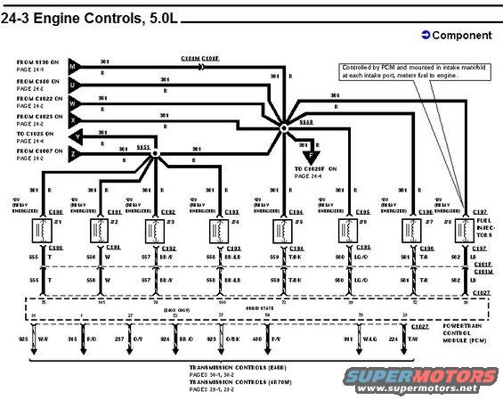
Ford factory wiring schematic page headed "24-3 Engine Controls, 5.0L," showing the fuel injector circuits for cylinders #1 through #8 fed from splice S143/S151 and driven by the powertrain control module. A callout notes the injectors are PCM-controlled and mounted in the intake manifold at each intake port, with references to E4OD and 4R70W transmission control pages.

AI caption · Photo 309 of 378

Is this accurate? Sign in to help verify it.

Comments

No comments yet.

More from this build

Ford 5.8L California engine controls wiring diagram page 25-12, inertia fuel shutoff and fuel pump module Ford 5.8L California engine controls wiring diagram page 25-11, malfunction indicator lamp and HO2S Ford 5.8L California engine controls wiring diagram page 25-10, IAT sensor and heated oxygen sensor Ford 5.8L California engine controls wiring diagram page 25-9, EGR, ECT, TP and EGR valve position sensors Ford 5.8L California engine controls wiring diagram page 25-8, fuel injectors and idle air control circuits Ford 5.8L California engine controls wiring diagram page 25-7, PCM power relay and fuel pump circuits Vehicle Speed Sensor (VSS) wiring diagram, Bronco, page 64-2, rear axle sensor and PSOM circuits Vehicle Speed Sensor (VSS) wiring diagram, F-Series, page 64-1, rear axle sensor and PSOM circuits

More 1992-1996 Broncos